Eureka AIR delivers breakthrough ideas for toughest innovation challenges, trusted by R&D personnel around the world.

Method and system for controlling a heat transfer apparatus

Active Publication Date: 2014-09-25
SAUNDERS CARLETON E IV
View PDF5 Cites 0 Cited by
  • Summary
  • Abstract
  • Description
  • Claims
  • Application Information

AI Technical Summary

Benefits of technology

This patent describes a heat transfer apparatus with a control system and a casing. The casing is designed to mimic the temperature of the heat transfer product being controlled. The casing seal prevents air from flowing into the chamber and allows the casing to accommodate different thermal sensors with varying diameters. The casing further includes a fluid chamber enclosed between the inner and outer casing walls, which may contain a fluid to match the temperature of the product being controlled. The system also includes a control apparatus and a heat transfer apparatus for use in heat transfer processes. The casing is made of plastic or silicone foam and the thermal sensor is not in direct contact with the casing wall. The technical effects of this invention include improved control of heat transfer and better protection of the thermal sensor during transport and installation.

Problems solved by technology

This is problematic because the ultimate goal of the refrigeration system is to maintain product temperature, and air temperature fluctuates much more rapidly than product temperature, thus creating creating premature compressor starts and stops.
These premature compressor starts and stops create unnecessarily high fluctuations in product temperature, increase mechanical shock on the system, and create significant energy waste.

Method used


Image

  • Method and system for controlling a heat transfer apparatus
  • Method and system for controlling a heat transfer apparatus
  • Method and system for controlling a heat transfer apparatus

Examples


Embodiment Construction

[0015]In the following description, the use of “a,”“an,” or “the” can refer to the plural. All examples given are for clarification only and are not intended to limit the scope of the invention.

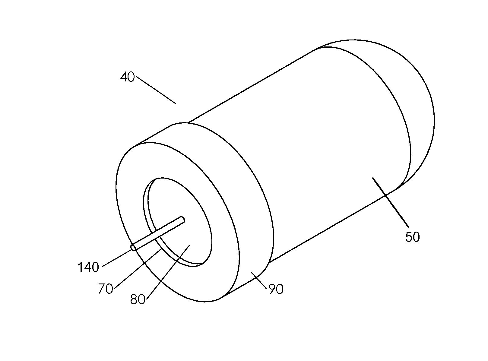
[0016]FIG. 1 is a diagrammatic view of a heat transfer apparatus 10 controlled by a control apparatus 20 comprising a thermal sensor 30. The heat transfer apparatus 10 may comprise any device or system known in the art for moving or transferring heat, including but not limited to a refrigerator, air conditioner, freezer, heat pump, etc. In the embodiment described herein, heat transfer apparatus 10 may comprise a refrigerator having, for example, an enclosed fluid conduit, a working medium within the conduit, a fluid pump, a condenser, and an evaporator. Control apparatus 20 may comprise any device, system, processor, or computer that is known in the art and is configured, through any means known (such as via mechanical components, electrical components, hydraulics, pneumatics, etc.), to cont...


PUM

PropertyMeasurementUnit
Thicknessaaaaaaaaaa
Thicknessaaaaaaaaaa
Temperatureaaaaaaaaaa

Abstract

A method of controlling a heat transfer apparatus comprising the steps of: providing a heat transfer apparatus; providing a control apparatus comprising a thermal sensor configured to control operation of the heat transfer apparatus; providing a casing comprising a casing wall enclosing a casing chamber, a casing entrance, and a casing seal; and inserting the thermal sensor into the casing chamber through the casing entrance an aperture in the casing seal.

Description

FIELD OF THE INVENTION[0001]The present invention relates to a method and system for controlling a heat transfer apparatus and, more particularly, to an a method and system for increasing the operational efficiency of the heat transfer apparatus.BACKGROUND OF THE INVENTION[0002]Since the early 1800s, first generation refrigeration systems have accomplished heat exchange via a vapor compressor controlled by a thermostat receiving air temperature data from inside the refrigeration cabinet via a thermal sensor. This is problematic because the ultimate goal of the refrigeration system is to maintain product temperature, and air temperature fluctuates much more rapidly than product temperature, thus creating creating premature compressor starts and stops. These premature compressor starts and stops create unnecessarily high fluctuations in product temperature, increase mechanical shock on the system, and create significant energy waste.SUMMARY OF THE INVENTION[0003]According to one embod...

Claims


Application Information

Patent Timeline
IPC IPC(8): F28F27/00F28F9/00B23P15/26
CPCF28F27/00F28F9/00B23P15/26F25B49/02F25D29/005F25B2700/2104F25D2700/12G01K13/00G01K2007/422G01K2207/04Y10T29/4935
Inventor O'NEILL, TOM
Owner SAUNDERS CARLETON E IV
Why Eureka
Eureka Blog
Learn More