Suspension system for in-wheel motor vehicle

a suspension system and motor vehicle technology, applied in the direction of shock absorbers, electric propulsion mountings, transportation and packaging, etc., can solve the problems of causing vehicle passengers to feel uncomfortable, vibration occurs, vibration is generally occurring, etc., to prevent vibration from becoming considerable, the effect of reducing vibration

Inactive Publication Date: 2014-09-25
NTN CORP
View PDF22 Cites 18 Cited by
  • Summary
  • Abstract
  • Description
  • Claims
  • Application Information

AI Technical Summary

Benefits of technology

[0015]According to the present invention, the resonance monitoring unit 21 monitors whether or not the rotational speed of the motor 7 falls within the resonance frequency range that is defined as a range which coincides with the natural frequency of the suspension 3. In the event that it is determined by the resonance monitoring unit 21 that the rotational speed of the motor 7 falls within the resonance frequency range, the elastic modulus control unit 22 applies the command to the drive source 10a of the elastic support mechanism 10 in the suspension 3 to change the modulus of elasticity. When the rotational speed of the motor 7 coincides with the natural frequency of the suspension 3, resonance takes place, which leads to a considerable vibration to such an extent as to cause vehicle passengers to feel discomfort, but the change of the modulus of elasticity of the suspension 3 is effective to avoid the resonance and the vibration becoming considerable enough to cause the vehicle passengers to feel discomfort.
[0016]The resonance monitoring unit 21 may have, as the resonance frequency range, rotational speed synchronization frequency ranges, each of which is a frequency range having its center defined by one of the rotational speed of the motor 7 and frequencies of integral multiples of the rotational speed of the motor 7, and a cogging torque responsive frequency range, which is a frequency range corresponding to an electrical vibration generated by cogging torque of a motor rotor (a rotor of the motor 7) 7b, and the resonance monitoring unit 21 may determine that the rotational speed of the motor 7 falls within the resonance frequency range when the rotational speed of the motor 7 falls within one of the rotational speed synchronization frequency ranges and the cogging torque responsive frequency range. In this case, the resonance with either one of a mechanical vibration resulting from an unbalance of the motor rotor 7b and an electrical vibration brought about by the cogging torque of the motor 7 can be avoided and it becomes possible to prevent the vibration becoming considerable enough to cause the vehicle passengers to feel discomfort.
[0017]In a preferred embodiment of the present invention, a damping force of the shock absorber 11 may be adjustable by a drive source, and the suspension system may further comprise a damping force control unit 23 to apply a command to change the damping force to the drive source 11a of the shock absorber 11 when the resonance monitoring unit 21 determines that the rotational speed of the motor 7 falls within the resonance frequency range. While the damping force of the shock absorber 11 is preferably high in terms of the reduction of the vibration, but if the damping force is high, it may occur that the traveling stability may be hardly obtained. When the damping force of the shock absorber 11 is changed, for example, the damping force is increased in the event that the rotational speed of the motor 7 is determined falling within the resonance frequency range as discussed above, the travelling stability is secured during a normal time with the damping force of the suspension 3 reduced and only when the vibration is generated by the resonance, the damping force is increased to reduce the vibration. In the practice of the present invention, in the event of the motor rotational speed that may result in resonance, the modulus of elasticity of the elastic support mechanism 10 is changed as described above to thereby avoid the resonance, but it may occur that it is not sufficiently avoided. When the resonance is not sufficiently avoided as discussed above, the damping force of the shock absorber 11 is increased to absorb the vibration and, therefore, it is possible to prevent the vibration becoming considerable enough to cause the vehicle passengers to feel discomfort.
[0018]In another preferred embodiment of the present invention, the suspension system may further comprise a running condition responsive non-permitting unit 24 to determine whether or not a predetermined change non-permitting condition is true based on one or a plurality of signals out from a signal indicative of a speed of the vehicle equipped with the suspension 3, a signal indicative of an angular acceleration of the vehicle, a braking signal in the vehicle, a steering angle signal in the vehicle and a signal indicative of a stroke position of the shock absorber 11, and to proscribe a control by the elastic modulus control unit 22 when the predetermined change non-permitting condition is true. The angular acceleration is an angular acceleration such as, for example, a rolling, a pitching and a yawing, all occurring in the vehicle. When straight traveling at a constant speed, no acceleration such as the rolling and others is generated in the vehicle and, therefore, the vehicle attitude will not be disturbed even when the modulus of elasticity is changed. However, since various forces such as the rolling, the yawing and others act during the cornering, not only is the vehicle attitude disturbed when the modulus of elasticity is markedly changed, but a risk of getting out of the course will occur. For this reason, by detecting a condition of the vehicle from the vehicle speed (the speed of the vehicle), the brake operation, the steering angle and other and by performing no control to change the modulus of elasticity in the event of, for example, the speed and the angular acceleration exceeding a certain value, the vehicle attitude can be prevented from being disturbed.

Problems solved by technology

Since the in-wheel motor device is disposed below a suspension unlike an electric automobile of a single motor type in which the motor is mounted on a chassis that is supported through a suspension, two types of vibrations occur in the in-wheel motor device as a result of rotation of the motor and those vibrations are apt to be transmitted to a vehicle body structure, thus tending to make vehicle passengers to feel uncomfortable.
In the in-wheel motor device equipped with the above described reduction gear, this vibration generally occurs when the vehicle running speed is a medium speed and a high speed.
This vibration occurs when the vehicle running speed is an extremely low speed such as used during, for example, putting the vehicle into a garage.
Each of those vibrations is resonated when it coincides with a natural frequency of the suspension to increase and will often become a vibration by which the vehicle passengers may feel uncomfortable.

Method used


Image

  • Suspension system for in-wheel motor vehicle
  • Suspension system for in-wheel motor vehicle
  • Suspension system for in-wheel motor vehicle

Examples


Embodiment Construction

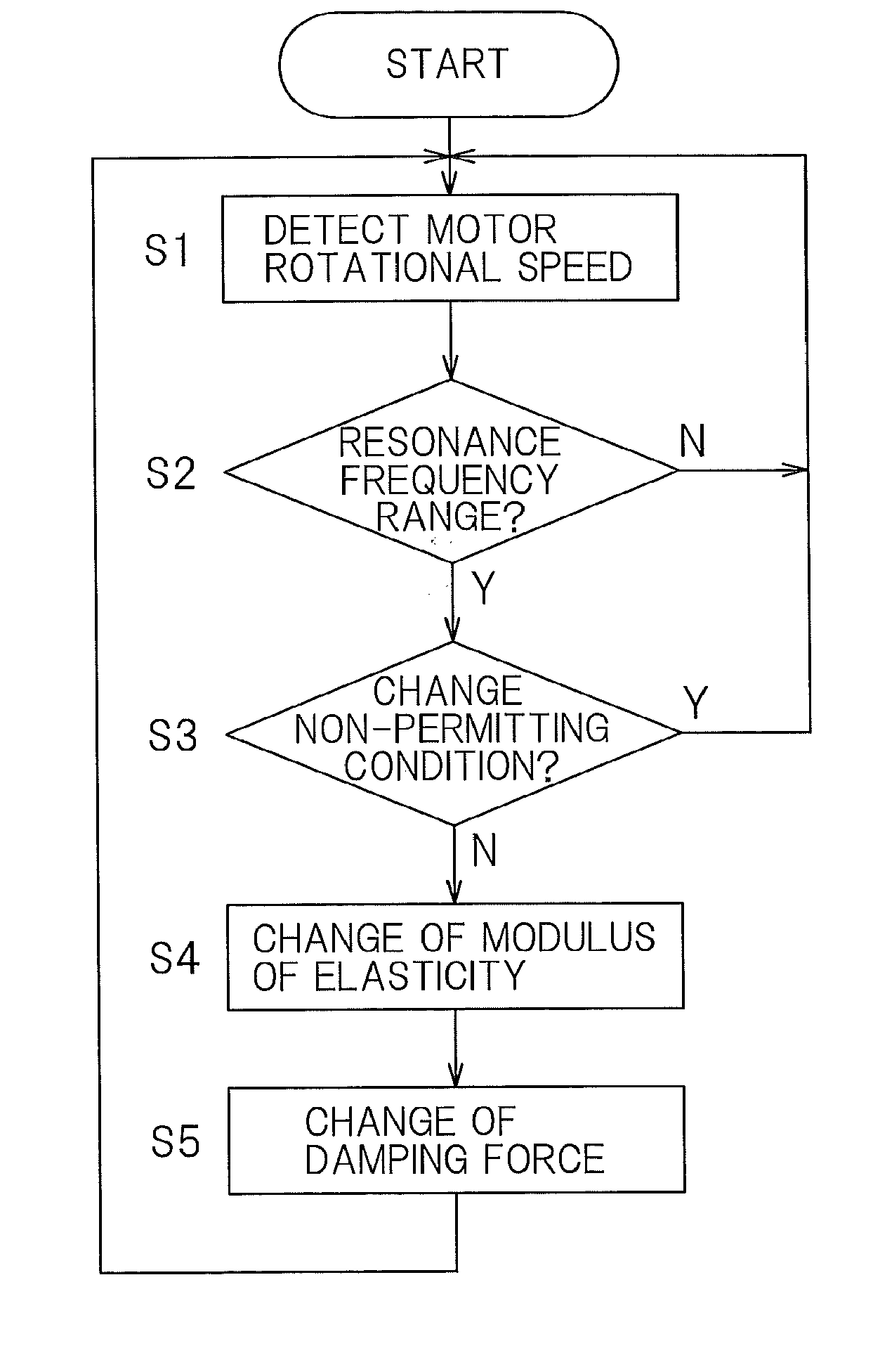
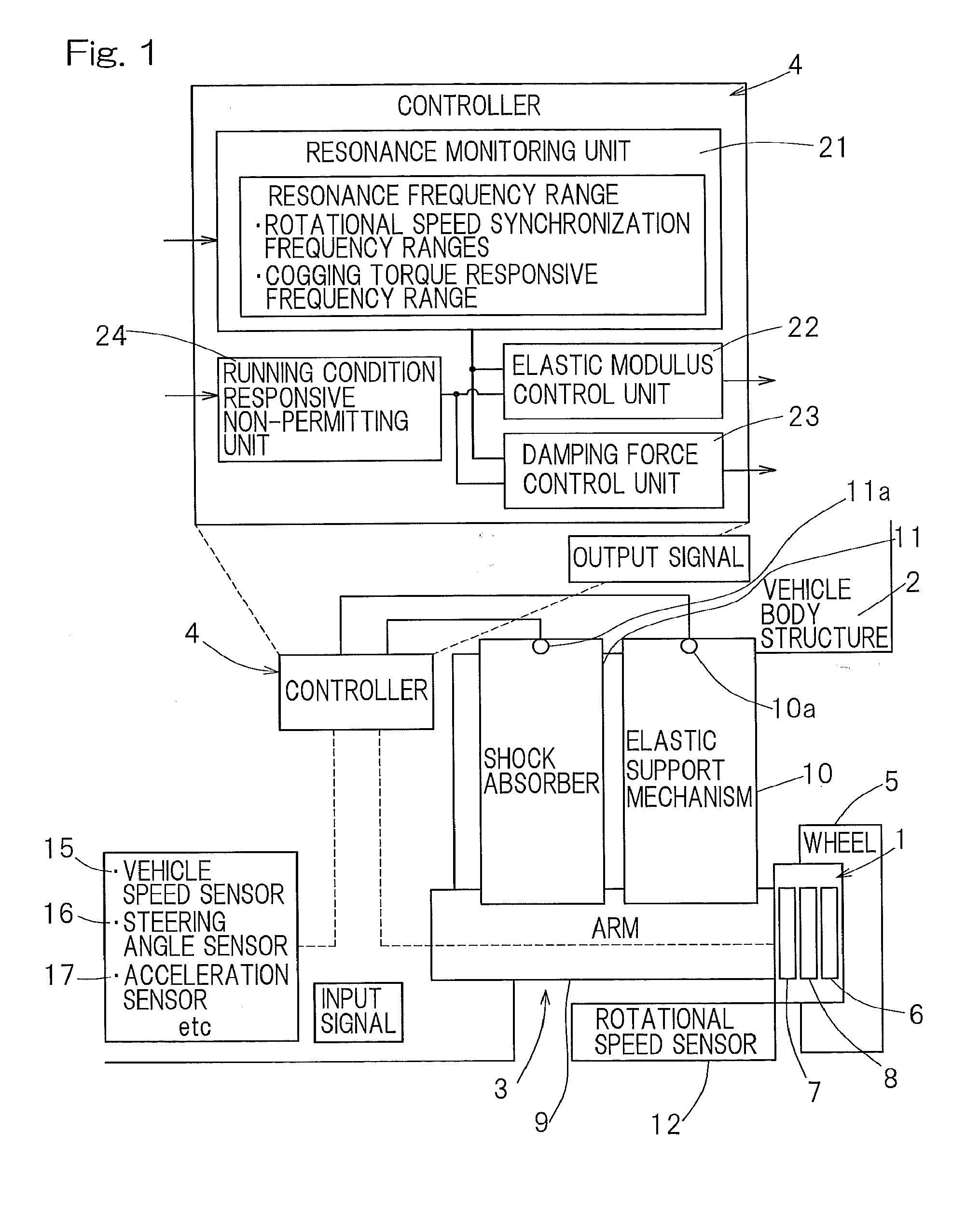
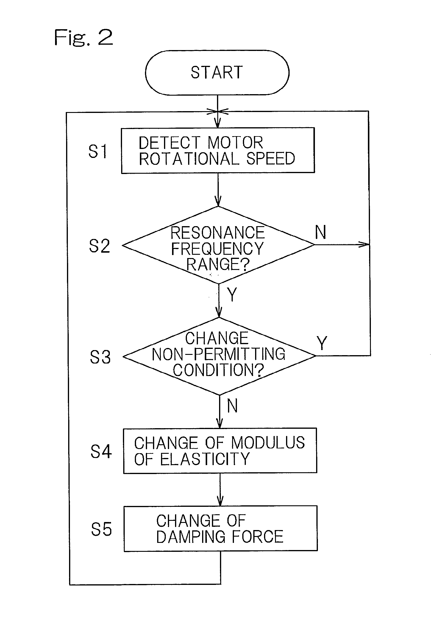
[0027]A preferred embodiment of the present invention will be described in detail with reference to the accompanying drawings. A suspension system for an in-wheel motor mounted vehicle according to the present invention includes a suspension 3 interposed between an in-wheel motor device 1 and a vehicle body structure 2, and a controller 4 to control the modulus of elasticity and the damping force of the suspension 3.

[0028]The in-wheel motor device 1 includes, as shown in, for example, FIG. 3, a wheel support bearing assembly 6 to support a wheel 5, a motor 7, and a reduction gear 8 to transmit the rotation of the motor 7 to a rotatable side raceway of the wheel support bearing assembly 6. The wheel support bearing assembly 6 is of a type in which a plurality of rows of rolling elements 33 are interposed between an outer member 31, which will become a stationary side raceway, and an inner member 32, which will become the movable side raceway, and a rim for the wheel 5 is fitted to a ...


PUM


Abstract

Included are an elastic support mechanism (10) and a shock absorber (11) in a suspension (3) interposed between an in-wheel motor device (1) and a vehicle body structure (2). The elastic support mechanism (10) can change a modulus of elasticity and the shock absorber (11) can change a damping force. The provision is made of a resonance monitoring unit (21) to monitor whether or not a rotational speed of a motor (7) falls within a predetermined resonance frequency range. When the rotational speed of the motor (7) is determined as falling within the resonance frequency range, an elastic modulus control unit (22) changes the modulus of elasticity, and a damping force control unit (23) changes the damping force of the shock absorber (11).

Description

CROSS REFERENCE TO THE RELATED APPLICATION[0001]This application is based on and claims Convention priority to Japanese patent application No. 2011-241108, filed Nov. 2, 2011, the entire disclosure of which is herein incorporated by reference as a part of this application.BACKGROUND OF THE INVENTION[0002]1. Field of the Invention[0003]The present invention relates to a suspension system for a vehicle employing in an in-wheel motor used to drive such vehicle and, more particularly, to the suspension system of a kind in which vibrations peculiar to the in-wheel motor mounted vehicle.[0004]2. Description of Related Art[0005]As a suspension system for an automobile, the electronically controlled suspension system designed to improve the riding quality and the roadability has been suggested in, for example, the non-patent document 1 listed below, which system controls in dependence on the running condition while the spring constant or the damping force is made variable.PRIOR ART LITERATU...

Claims


Application Information

Patent Timeline
Patent Type & Authority Applications(United States)
IPC IPC(8): B60G17/016
CPCB60G3/20B60G17/019B60G17/02B60G17/06B60G2204/182B60G2400/91B60G17/016B60G2500/20B60K7/0007B60K17/046B60K2007/0038B60K2007/0092F16F9/535B60G2500/10
Inventor HIRATA, JUNICHI
Owner NTN CORP
Why Eureka
Try Eureka