Electric power conversion apparatus

a technology of electric power conversion and capacitor, which is applied in the direction of printed circuit board receptacles, basic electric elements, support structure mounting, etc., can solve the problems of shortening increasing difficult to minimize the size of the case, so as to effectively suppress the increase in the temperature of the capacitor, prolong the service life of the capacitor, and suppress the effect of the capacitor temperature increas

Active Publication Date: 2014-09-25
DENSO CORP
View PDF0 Cites 25 Cited by
  • Summary
  • Abstract
  • Description
  • Claims
  • Application Information

AI Technical Summary

Benefits of technology

[0010]With the above configuration, the frame has the capacitor-surrounding wall surrounding the capacitor. Consequently, with the capacitor-surrounding wall, it is possible to block external heat which otherwise would be transmitted to the capacitor via the case. As a result, it is possible to suppress increase in the temperature of the capacitor, thereby extending the service life of the capacitor.
[0011]Moreover, with the above configuration, the frame also has the stacked body-surrounding wall surrounding the stacked body which has the coolant passages formed therein. Consequently, the metal frame and thus the capacitor-surrounding wall of the frame can be cooled by a coolant that flows through the coolant passages. As a result, with the capacitor-surrounding wall being cooled by the coolant, it is possible to more effectively suppress increase in the temperature of the capacitor, thereby more reliably extending the service life of the capacitor.
[0012]Furthermore, with the above configuration, the end portions of the capacitor in the predetermined direction are each at least partially exposed from the ca...

Problems solved by technology

However, with the above configuration, when there are electronic devices arranged in the vicinity of the electric power conversion apparatus, heat generated by the electronic devices will be transmitted to the capacitor via the case, thereby increasing the temperature of the capacitor.
Further, the increase in the temp...

Method used


Image

  • Electric power conversion apparatus
  • Electric power conversion apparatus
  • Electric power conversion apparatus

Examples


first embodiment

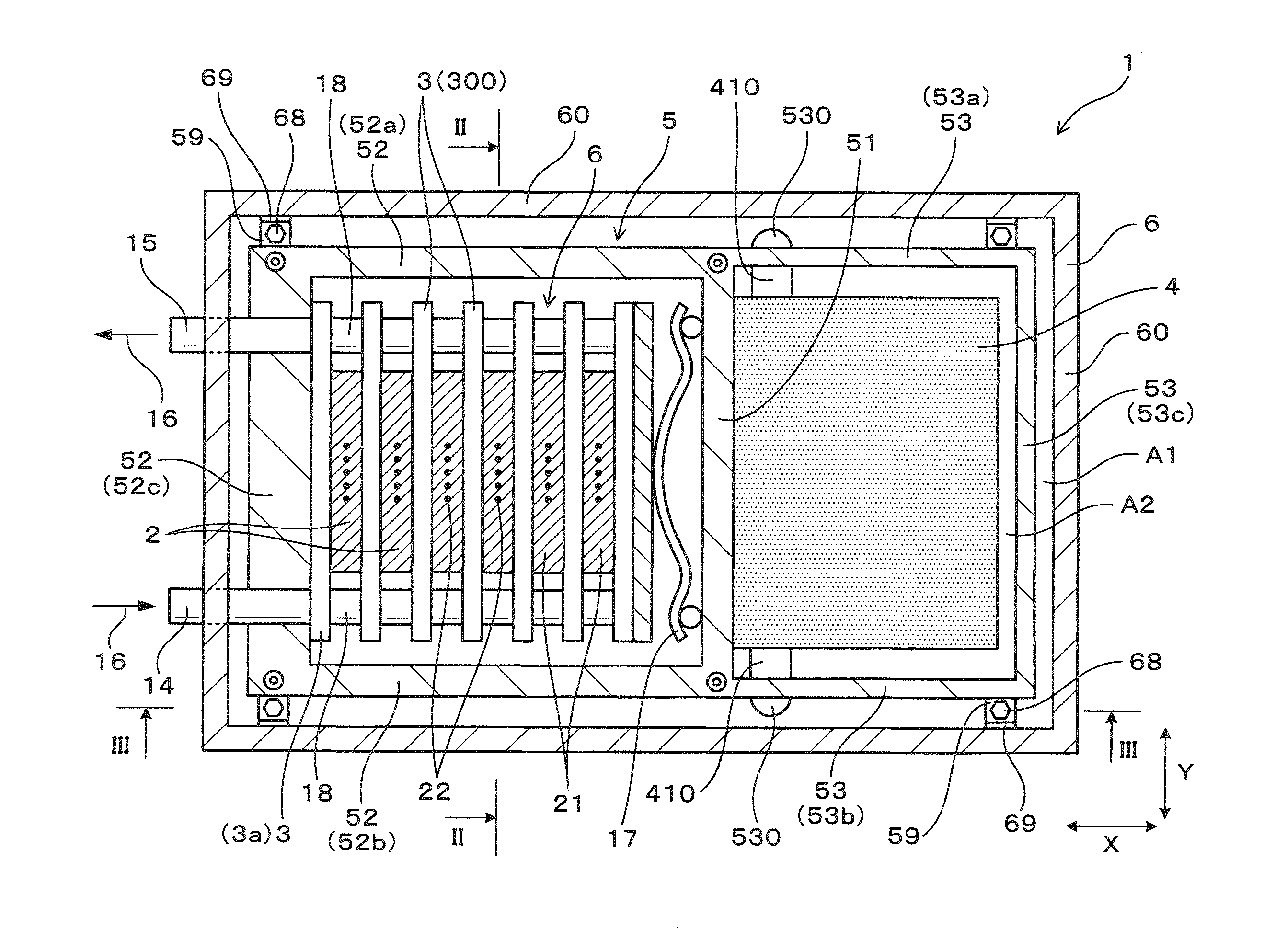
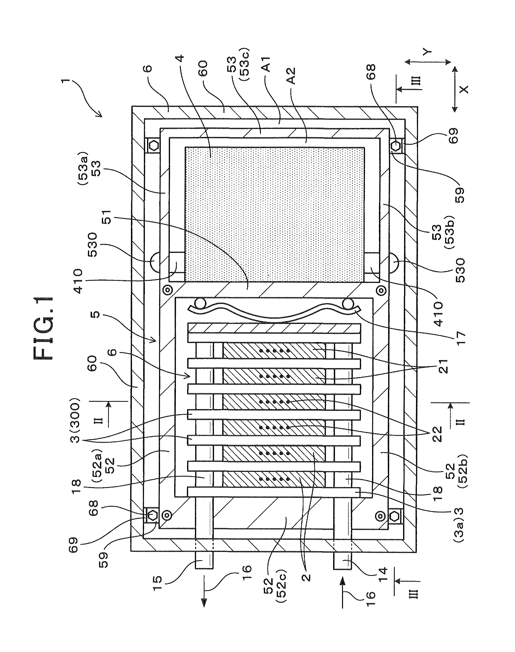
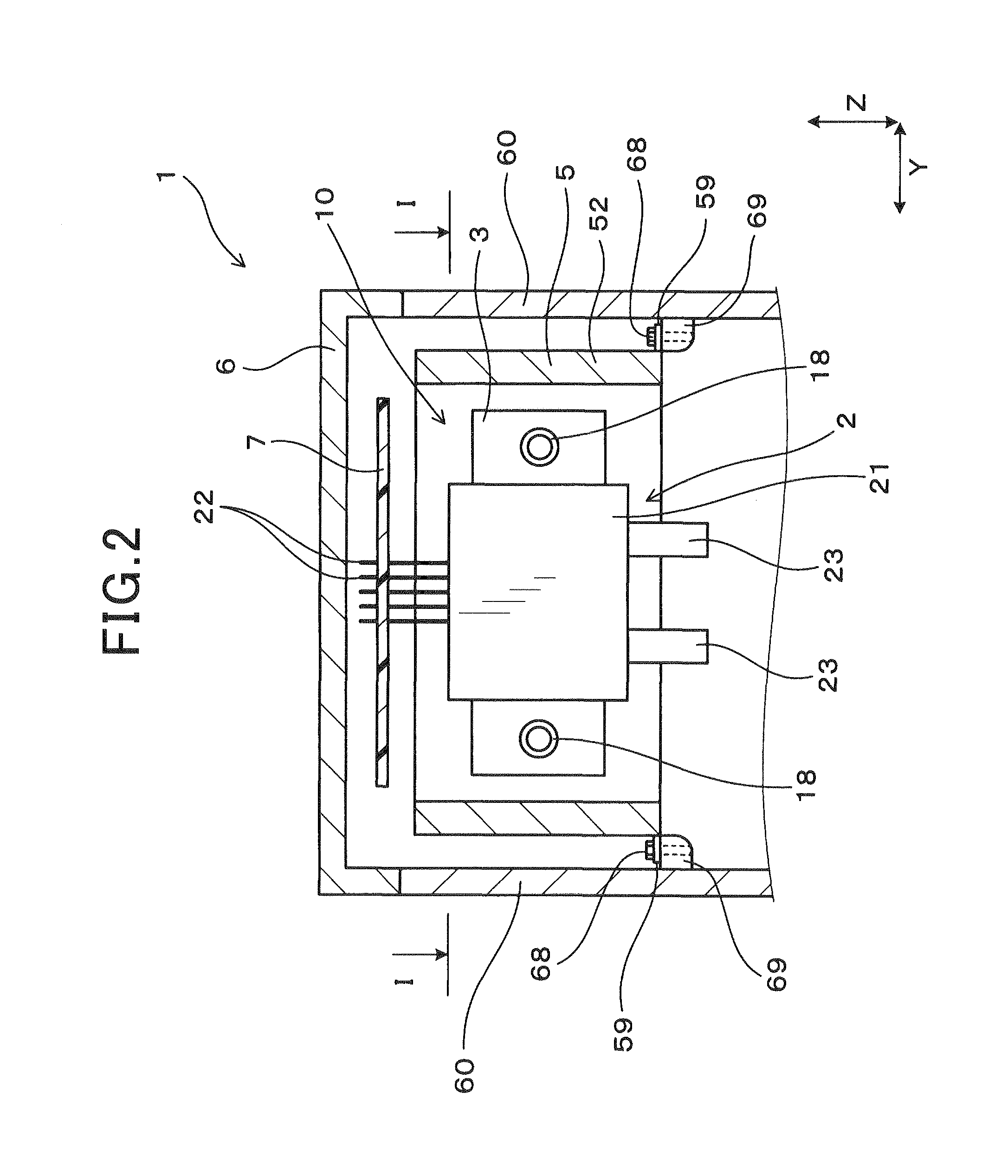
[0033]FIGS. 1-3 together show the overall configuration of an electric power conversion apparatus 1 according to a first embodiment.

[0034]In the present embodiment, the electric power conversion apparatus 1 is configured as a vehicular electric power conversion apparatus to be used in, for example, an electric vehicle or a hybrid vehicle. Therefore, in the use of the electric power conversion apparatus 1, there are heat-generating devices or machines, such as a motor and an internal combustion engine, around the apparatus 1.

[0035]As shown in FIGS. 1-3 the electric power conversion apparatus 1 includes a stacked body 10, a capacitor (or electrical condenser) 4, a metal frame 5 and a case 6.

[0036]The stacked body 10 is formed by stacking a plurality of semiconductor modules 2 alternately with a plurality of cooling devices 3 in an X direction as shown in FIGS. 1 and 3. Each of the semiconductor modules 2 includes a main body 21, which has semiconductor elements 20 (shown in FIG. 4) bu...

second embodiment

[0075]This embodiment illustrates an electric power conversion apparatus 1 which has almost the same configuration as the electric power conversion apparatus 1 according to the first embodiment; accordingly, only the differences therebetween will be described hereinafter.

[0076]In the first embodiment, the capacitor-surrounding wall 53 of the frame 5 is formed so that opposite ends of the capacitor-surrounding wall 53 in the Z direction are respectively positioned on opposite sides of the center position of the separation wall 51 of the frame 5 in the Z direction. Moreover, the capacitor 4 is fixed in the frame 5 so that the upper end surface of the capacitor 4 is positioned flush with the upper end surface of the separation wall 51 of the frame 5, and the lower end surface of the capacitor 4 is positioned lower than the lower end surface of the separation wall 51. Accordingly, the clearance provided between the control circuit board 7 and the capacitor 4 in the Z direction is equal ...

third embodiment

[0080]This embodiment illustrates an electric power conversion apparatus 1 which has almost the same configuration as the electric power conversion apparatus 1 according to the first embodiment; accordingly, only the differences therebetween will be described hereinafter.

[0081]In the first embodiment, the length of the capacitor 4 in the Z direction is set so that only the lower end surface of the capacitor 4 protrudes downward from the lower end surface of the separation wall 51 of the frame 5 with the upper end surface of the capacitor 4 flush with the upper end surface of the separation wall 51. Moreover, the length of the control circuit board 7 in the X direction is set so that the control circuit board 7 covers both the stacked body 10 and the capacitor 4 (see FIG. 3).

[0082]In comparison, in the present embodiment, as shown in FIG. 9, the length of the control circuit board 7 in the X direction is reduced so that the control circuit board 7 covers only the stacked body 10. In ...


PUM


Abstract

An electric power conversion apparatus includes a stacked body, a capacitor, a metal frame and a case. The stacked body is formed by stacking semiconductor modules with coolant passages formed therebetween. The frame has both the stacked body and the capacitor fixed therein. The case has all of the stacked body, the capacitor and the frame received therein. Further, the frame has a separation wall that separates the stacked body and the capacitor from each other, a stacked body-surrounding wall that surrounds the stacked body with the help of the separation wall, and a capacitor-surrounding that surrounds the capacitor with the help of the separation wall. The capacitor has a pair of end portions that are opposite to each other in a predetermined direction, in which control terminals of the semiconductor modules of the stacked body protrude, and each at least partially exposed from the capacitor-surrounding wall of the frame.

Description

CROSS-REFERENCE TO RELATED APPLICATION[0001]This application is based on and claims priority from Japanese Patent Application No. 2013-61467 filed on Mar. 25, 2013, the content of which is hereby incorporated by reference in its entirety into this application.BACKGROUND[0002]1. Technical Field[0003]The present invention relates to an electric power conversion apparatus that includes a stacked body, a capacitor and a metal frame; the stacked body is formed by stacking a plurality of semiconductor modules and has a plurality of coolant passages formed between the semiconductor modules.[0004]2. Description of the Related Art[0005]There is disclosed, for example in Japanese Unexamined Patent Application Publication No. 2011-182626, an electric power conversion apparatus that performs electric power conversion between DC (Direct Current) power and AC (Alternating Current) power.[0006]Specifically, the electric power conversion apparatus is configured to include a stacked body, a metal fr...

Claims


Application Information

Patent Timeline
IPC IPC(8): H01L23/34H01L49/02
CPCH01L28/40H01L23/34H01L23/4012H01L23/473H01L2924/0002H02M7/003H01L25/117H01L2924/00H05K7/1427H02M7/537
Inventor KIUCHI, YUUYANAKASAKA, AKIRA
Owner DENSO CORP
Why Eureka
Try Eureka