Bucking circuit for annulling a magnetic field

a magnetic field and annulling circuit technology, applied in the field of bucking systems, can solve the problems of in-phase component of scattered response that may be poorly rendered, measurement to the off-time, loss of information, etc., and achieve the effect of reducing the degree of rigidity, reducing the size of the bucking volume and less rigidity

Active Publication Date: 2014-09-25
VALE LIMITED
View PDF13 Cites 9 Cited by
  • Summary
  • Abstract
  • Description
  • Claims
  • Application Information

AI Technical Summary

Benefits of technology

[0049]The foregoing examples have illustrated various possible uses of the present invention systems with a flexible geometry. However, the present invention may also be advantageously employed in so-called rigid geometry AEM systems, in which the geometry of the transmitter, bucking and receiver loops are nearly rigidly mounted with respect to one another, an examples of which is the Aerotem system. Such systems may experience drift, a component of which may be due to small geometrical variations, caused for example by small dimensional changes in the rigid supports. The effect of such changes may be diminished with the present invention by permitting the size of the bucked volume to be increased, and thus reducing the degree rigidity required Since the rigidity requirement in airborne systems limits the size of the system due to the weight of the rigid supports, the present invention may be advantageously employed in such rigid systems by either permitting the system to be lightened with less rigidity, so reducing the operating costs, or by extending the dimensions of the system, so improving the quality of the EM data.
[0050]A first aspect the present invention refers to a bucked transmitter, namely a transmitter which has its magnetic field substantially annulled over a bucked volume. Bucking is done with a field created by multiple bucking loops belonging to a bucking loop arrangement, so the field may be annulled over a volume to a greater degree than can be accomplished with a single bucking loop.
[0051]The bucked transmitter comprises the bucking loop arrangement and a transmitter sending a known current waveform into a transmitter loop mounted on a substantially rigid framework. The bucking loop arrangement comprises a plurality of separate, electrically conducting bucking loops mounted on a bucking loop support, so that the bucking loops are held in place with respect to each other, and substantially in-place with respect to the transmitter loop. Currents that are energized in the bucking loops, with a current controller having a waveform substantially similar to the transmitter waveform, create a bucking magnetic field which substantially annuls the primary magnetic field over a bucked volume. In one variation, this current controller may refer to the transmitter, with the transmitter and bucking loops in series, while in other variations, the each loop may be driven by a separate current controller. In any variation, the bucking magnetic field is substantially in a direction opposite to, and is substantially equal in magnitude with, the primary magnetic field within the bucked volume, such that the bucking magnetic field substantially annuls said primary magnetic field over a larger volume than could be done with a single loop. The transmitter currents and the bucking currents may be sensed with current monitors, with the currents recorded using a data recording means, such as a data acquisition computer. The substantially rigid transmitter loop framework may permit small motions of the transmitter loop from its nominal location, but is sufficiently rigid that the bucked volume is not displaced by a significant distance in comparison to its dimensions.
[0052]In a second aspect of the invention, related to field of electromagnetic surveying, an electromagnetic measurement apparatus comprises a bucked transmitter, a magnetic field sensor, and a receiver adapted for controlling said magnetic field sensor so as to permit the output of said sensor to be measured and recorded. The magnetic field sensor is located in the bucked volume, and is mounted on a sensor support frame comprising a mechanical support apparatus adapted to support and limit the motion of the sensor to within the bucked volume. The sensor support frame and the bucking loop support are connected to the substantially rigid transmitter loop framework. The magnetic field within the bucked volume, comprising the primary and bucking magnetic fields, may also comprise a component that is scattered by the primary field due to induction in the Earth. As the magnetic field sensor operates in a volume where the primary field is bucked by the secondary field, it may be operated at a finer resolution than would be otherwise possible, and so may be adapted for measuring the component of the magnetic field which may be scattered from the Earth.
[0053]In a third aspect of the invention, a mobile electromagnetic measurement apparatus comprises an electromagnetic measurement apparatus and a carrier to transport it. The mobile electromagnetic measurement apparatus may also comprise a means of transporting the carrier, a sensor to detect the position and orientation of the carrier such as a global positioning system, and a means of recording data, such as a data acquisition computer. For example, variations of this aspect of the present invention may comprise electromagnetic prospecting systems.
[0054]In fourth aspect of the current invention, the invention may comprise part of an active airborne electromagnetic system, in which the transmitter loop may be adapted to energize eddy currents within the Earth, the magnetic field sensor may be adapted to measure those eddy currents, and the bucking loops may be adapted to cancel the primary field of the transmitter loop on the magnetic field sensor without appreciably affecting either the eddy current distribution in the Earth or the sensitivity of the magnetic field sensor to the eddy current distribution in the Earth.

Problems solved by technology

The disadvantage of limiting measurement to the off-time is a loss of information.
In particular, the in-phase component of scattered response may be poorly rendered, with the result that certain highly conductive ores may be undetectable.
As a result, the range of receiver positions over which the field may be bucked is usually also small.
The residuals are generally indistinguishable from the in-phase scattered field, and so may degrade the quality of the measured scattered response.
Nevertheless, some unbucked residuals may occur, even in a system with a nominally nearly rigid geometry.
Polzer noted that the rotation of an EM sensor in the background magnetic field of the Earth, particularly in the 1-25 Hz low frequency range, creates noise which had previously prevented the acquisition of high-precision airborne electromagnetic data in that band.
Flexible systems permit a larger transmitter moment and logistical advantages, but with less perfect bucking, and less accurate measurement of the in-phase component of the scattered field as a consequence.
Less accurate in-phase measurements may result in poorer resolution of highly conductive geological features, many of which are targets of EM surveys commissioned for mining exploration.
However, flexure in the loop geometry causes shifts in the measured fields resulting from unbucked residuals of the primary field at the sensor.

Method used


Image

  • Bucking circuit for annulling a magnetic field
  • Bucking circuit for annulling a magnetic field
  • Bucking circuit for annulling a magnetic field

Examples


Embodiment Construction

[0026]The present invention improves the quality of the bucked primary field over the current state-of the-art single loop bucking where a magnetic field sensor may vary its location within a defined volume located relative to the transmitter loop. The present invention may also improve the quality of the bucked primary field where the position of a transmitter loop, or parts of it, may vary in relation to a bucking loop.

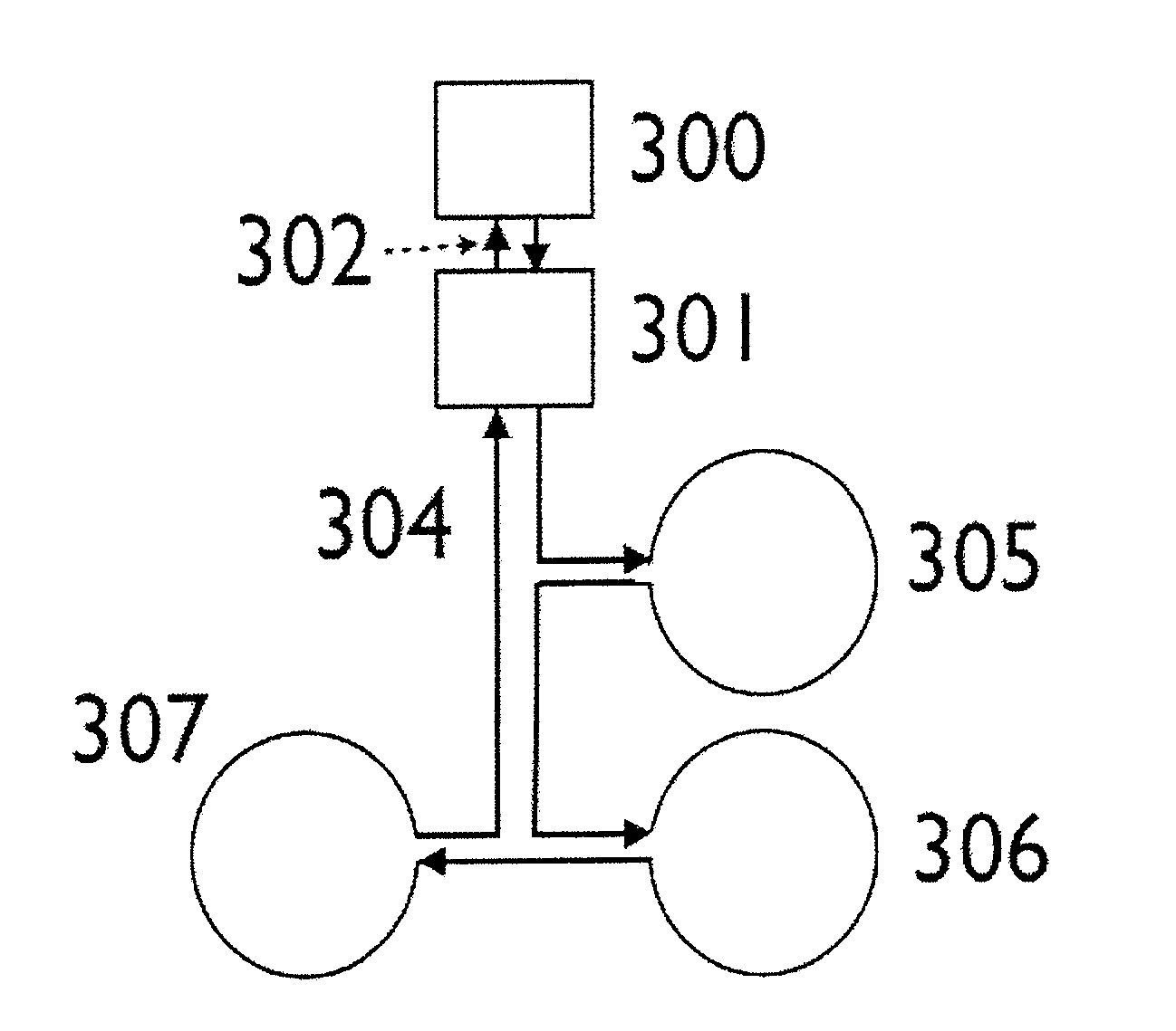
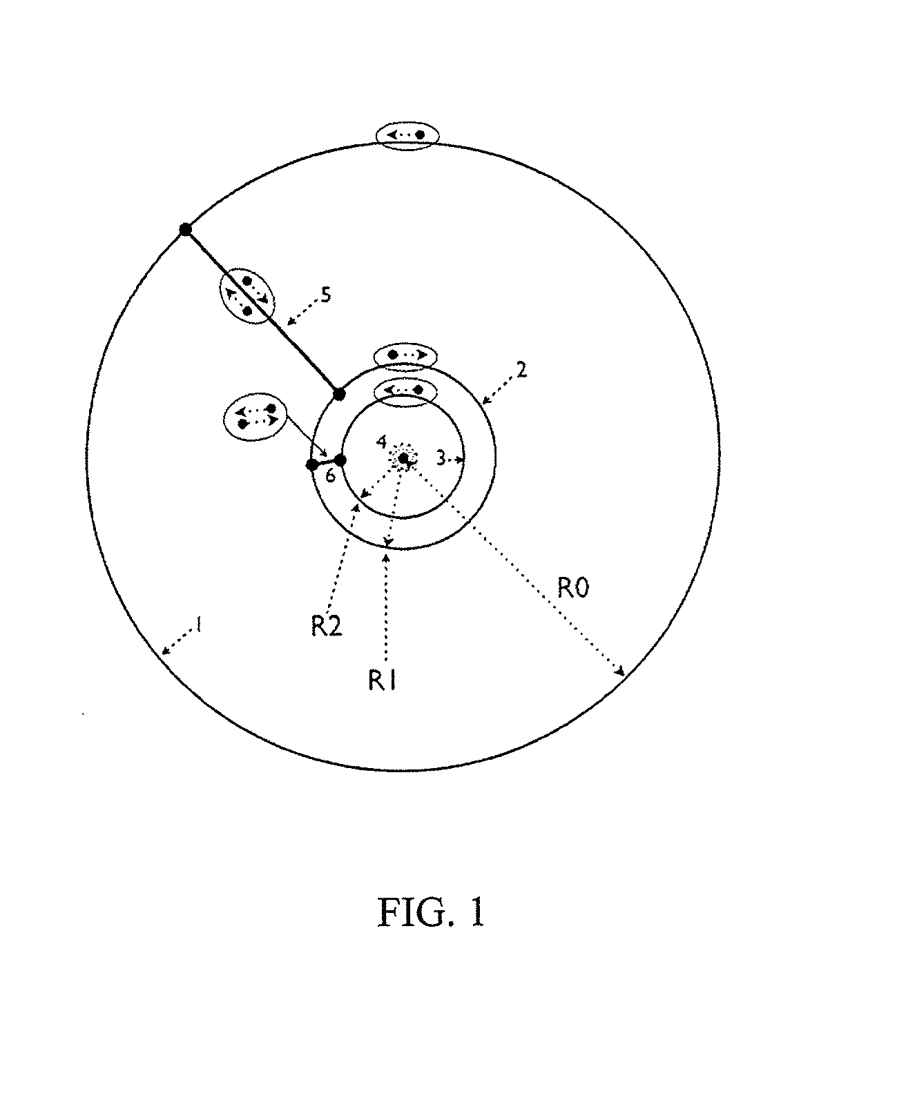
[0027]The present invention uses a plurality of coils or loops which are energized with electrical current to create a “bucking field” which substantially opposes the primary field on the magnetic field sensor. By employing a plurality of loops, substantial cancellation of the primary field may be effected over a larger volume than may be accomplished with a single loop. In so doing, the bucked field is less sensitive to changes in the system geometry than when a single bucking coil is used.

[0028]By using a plurality of loops in a “bucking loop arrangement”, the geo...


PUM


Abstract

A method and apparatus is provided for bucking a magnetic field of known geometry and time variation by means of a plurality of bucking loops. It utilizes multiple loops, each of which is energized by an electric current that creates a magnetic field of the known time variation. The multi-loop field forms a bucking magnetic field that better opposes the spatial variation in the known magnetic field over a volume than can the magnetic field from a single loop. The present invention is useful in electromagnetic measurements, where the magnetic field of a controlled source transmitter must be annulled at a magnetic field sensor. It is particularly useful for cases where the magnetic sensor may move relative to the transmitter, such as in certain airborne electromagnetic measurements.

Description

BACKGROUND OF THE INVENTION[0001]1. Field of the invention[0002]Aspects of this invention relate generally to bucking systems and to methods of substantially cancelling a magnetic field at points within a volume. More particularly, aspects of this invention may be used in electromagnetic prospecting to cancel the effect of a large transmitted field on a magnetic field sensor without appreciably modifying the interaction of the transmitted field with the ground. The current invention facilitates such cancellation when the sensor is displaced relative to the transmitter.[0003]2. Description of the Related Art[0004]Electromagnetic (“EM”) exploration methods comprise an important part of the geophysical methods used to map the Earth in the search of oil, gas and mineral deposits, aquifers and other geological features. EM methods can broadly categorized into two categories, passive source methods in which an electromagnetic survey apparatus is used to map naturally occurring time-variat...

Claims


Application Information

Patent Timeline
Patent Type & Authority Applications(United States)
IPC IPC(8): G01V3/28
CPCG01V3/28G01V3/107G01V3/165G01V3/38G01V3/30G01V3/18G01V3/26
Inventor WEST, GORDON FOXWALKER, PETER WHYTEPOLZER, BENJAMIN DAVID
Owner VALE LIMITED
Why Eureka
Try Eureka