Head-mounted display device and control method for head-mounted display device

a display device and display device technology, applied in the direction of instruments, computing, electric digital data processing, etc., can solve the problems of affecting work support, affecting the use of augmented reality, and affecting the visual field of the user's eyes,

Active Publication Date: 2014-09-25
SEIKO EPSON CORP
View PDF3 Cites 55 Cited by
  • Summary
  • Abstract
  • Description
  • Claims
  • Application Information

AI Technical Summary

Benefits of technology

[0009]An advantage of some aspects of the invention is to solve at least a part of the problems described above, and the invention can be implemented as the following aspects.

Problems solved by technology

However, when the user is about to start work keeping in mind the animation or the image displayed as a virtual image, the virtual image displayed in front of the eyes of the user is likely to block the visual field of the user and hinder the work.
Such a problem occurs not only in the work support that makes use of the augmented reality.
Such a problem is common to display of a virtual image in general in a head-mounted display device that enables a user to visually recognize a virtual image and an outside scene such as the transmissive head-mounted display device and the retina scanning type head-mounted display device.

Method used


Image

  • Head-mounted display device and control method for head-mounted display device
  • Head-mounted display device and control method for head-mounted display device
  • Head-mounted display device and control method for head-mounted display device

Examples


first embodiment

A. First Embodiment

A-1. Configuration of a Head-Mounted Display Device

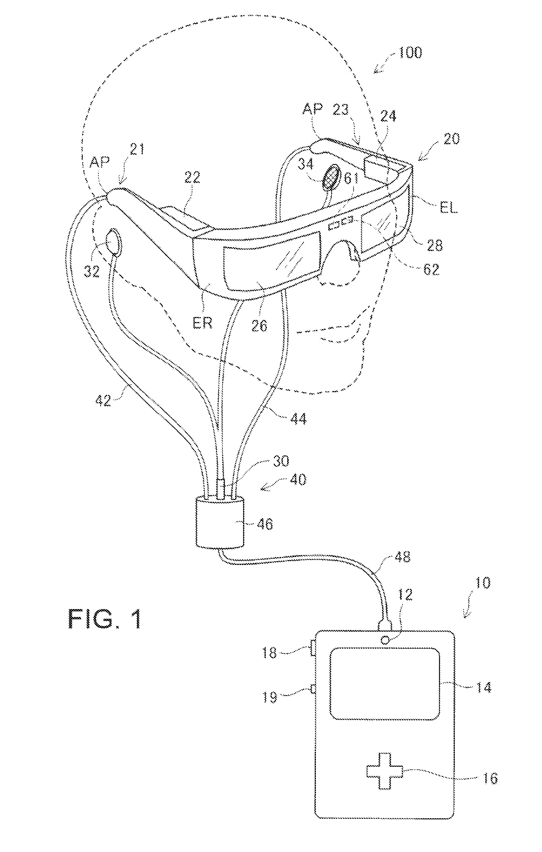
[0035]FIG. 1 is an explanatory diagram showing the schematic configuration of a head-mounted display device in a first embodiment of the invention. A head-mounted display device 100 is a display device mounted on the head and is also called head mounted display (HMD). The head mounted display 100 in this embodiment is an optically transmissive head-mounted display device that enables a user to visually recognize a virtual image and, at the same time, directly visually recognize an outside scene.

[0036]The head mounted display 100 includes an image display unit 20 configured to cause the user to visually recognize a virtual image in a state in which the image display unit 20 is mounted on the head of the user and a control unit (a controller) 10 configured to control the image display unit 20.

[0037]The image display unit 20 is a mounted body mounted on the head of the user. In this embodiment, the image display unit...

second embodiment

B. Second Embodiment

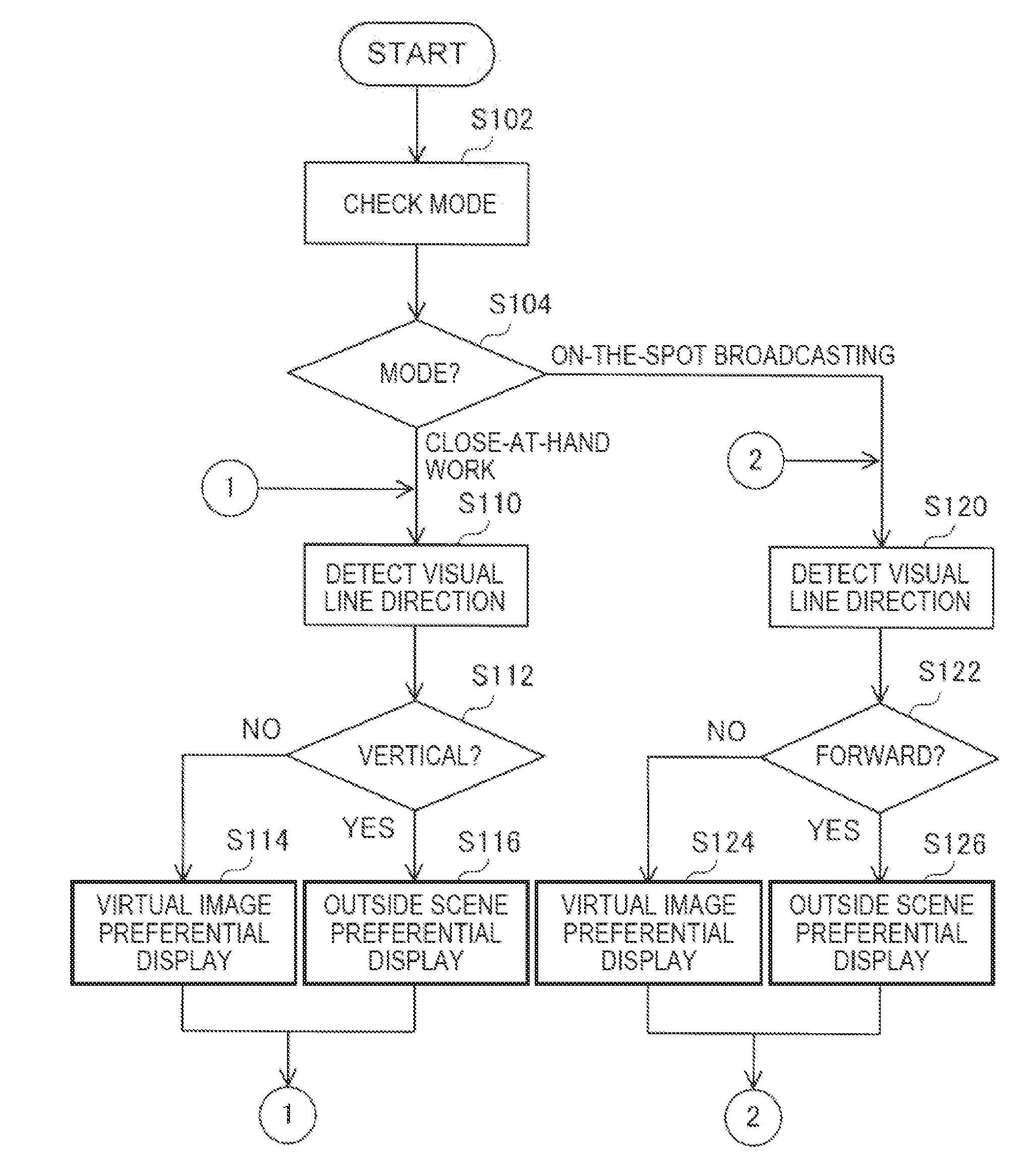
[0109]In a second embodiment of the invention, a configuration capable of changing detection sensitivity for a visual line direction of the user by a detecting unit according to a state of use of a head-mounted display device is explained. In the following explanation, only components including configurations and operations different from those in the first embodiment are explained. Note that, in the figures, components same as those in the first embodiment are denoted by reference numerals and signs same as those in the first embodiment explained above. Detailed explanation of the components is omitted.

B-1. Configuration of the Head-Mounted Display Device

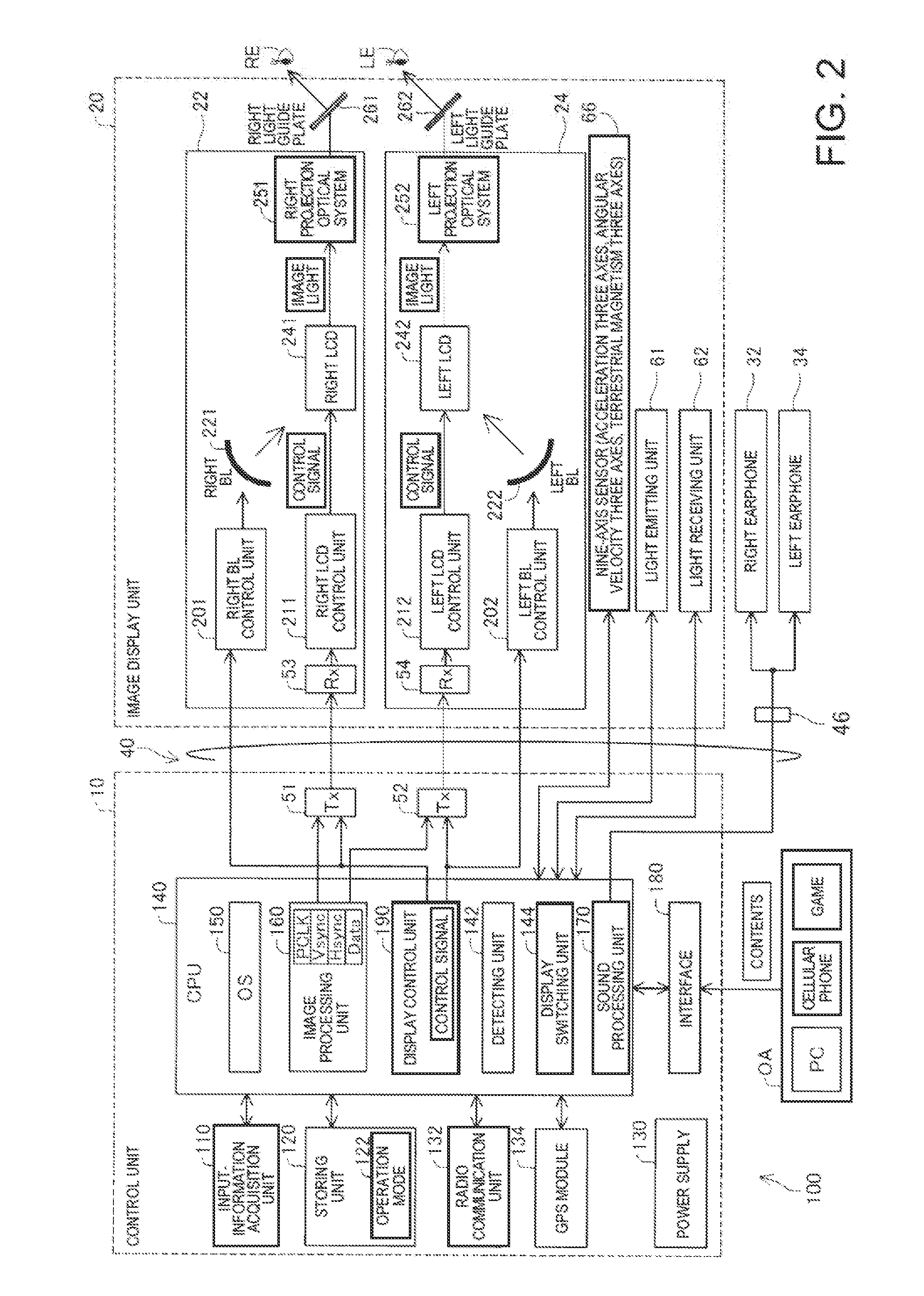
[0110]FIG. 11 is a block diagram functionally showing the configuration of a head mounted display 100a in the second embodiment. The head mounted display 100a is different from the head mounted display 100 in the first embodiment shown in FIG. 2 in that the head mounted display 100a includes a control unit 10a i...

modification 1

[0130]In the embodiment, the configuration of the head mounted display is illustrated. However, the configuration of the head mounted display can be arbitrarily set without departing from the spirit of the invention. For example, addition, deletion, conversion, and the like of the components can be performed.

[0131]The allocation of the components to the control unit and the image display unit in the embodiments is only an example. Various forms of the allocation can be adopted. For example, the following forms of the allocation may be adopted: (i) a form in which processing functions such as a CPU and a memory are mounted on the control unit and only a display function is mounted on the image display unit, (ii) a form in which the processing functions such as a CPU and a memory are mounted on both of the control unit and the image display unit, (iii) a form in which the control unit and the image display unit are integrated (e.g., a form in which the image display unit is included i...


PUM


Abstract

A head-mounted display device that enables a user to visually recognize a virtual image and an outside scene includes an image display unit configured to cause the user to visually recognize the virtual image, a detecting unit configured to detect a visual line direction of the user, and a display switching unit configured to switch, according to the detected visual line direction, display of the virtual image by the image display unit between outside scene preferential display for preferentially displaying the outside scene and virtual image preferential display for preferentially displaying the virtual image.

Description

BACKGROUND[0001]1. Technical Field[0002]The present invention relates to a head-mounted display device.[0003]2. Related Art[0004]There is known a technique called augmented reality (AR) for additionally presenting information in a real environment using a computer. As a method of realizing the augmented reality, a method by image recognition and a method based on a pass-through system are known. In the method by image recognition, information for additional presentation is generated by recognizing an image of an outside scene picked up by a WEB camera or the like. In the method based on the pass-through system, information for additional presentation is generated using present position information acquired by a GPS or the like and direction information acquired by an electronic compass or the like. In a non-transmissive head-mounted display device that blocks a visual field of a user when mounted, an image obtained by superimposing the image of the outside scene and the information ...

Claims


Application Information

Patent Timeline
Patent Type & Authority Applications(United States)
IPC IPC(8): G02B27/01
CPCG02B27/017G02B27/0179G02B2027/014G02B27/0093G06F3/013G06F3/011
Inventor KOBAYASHI, SHINICHI
Owner SEIKO EPSON CORP
Why Eureka
Try Eureka