Imprint template with optically-detectable alignment marks and method for making using block copolymers

Active Publication Date: 2014-09-25
WESTERN DIGITAL TECH INC
View PDF3 Cites 27 Cited by
  • Summary
  • Abstract
  • Description
  • Claims
  • Application Information

AI Technical Summary

Benefits of technology

[0015]The invention relates to a method using directed self-assembly of BCPs for making an imprint template that has the required patterns for both high density features in the active area and

Problems solved by technology

The making of a master imprint template is a difficult and challenging process.
However, a template capable of imprinting patterned-media disks with these small dimensions over an area equal to the active area of a disk may not be practical with the resolution of e-beam lithography.
Misalignment of any kind can cause short circuits and connection failures, which in turn impact fabrication yield and profit margins.
The alignment marks typically serve no functional purposes on finished devices.
However, due to the optical diffraction limit, optically detectable alignment marks need to have dimensions and pitch

Method used


Image

  • Imprint template with optically-detectable alignment marks and method for making using block copolymers
  • Imprint template with optically-detectable alignment marks and method for making using block copolymers
  • Imprint template with optically-detectable alignment marks and method for making using block copolymers

Examples


Embodiment Construction

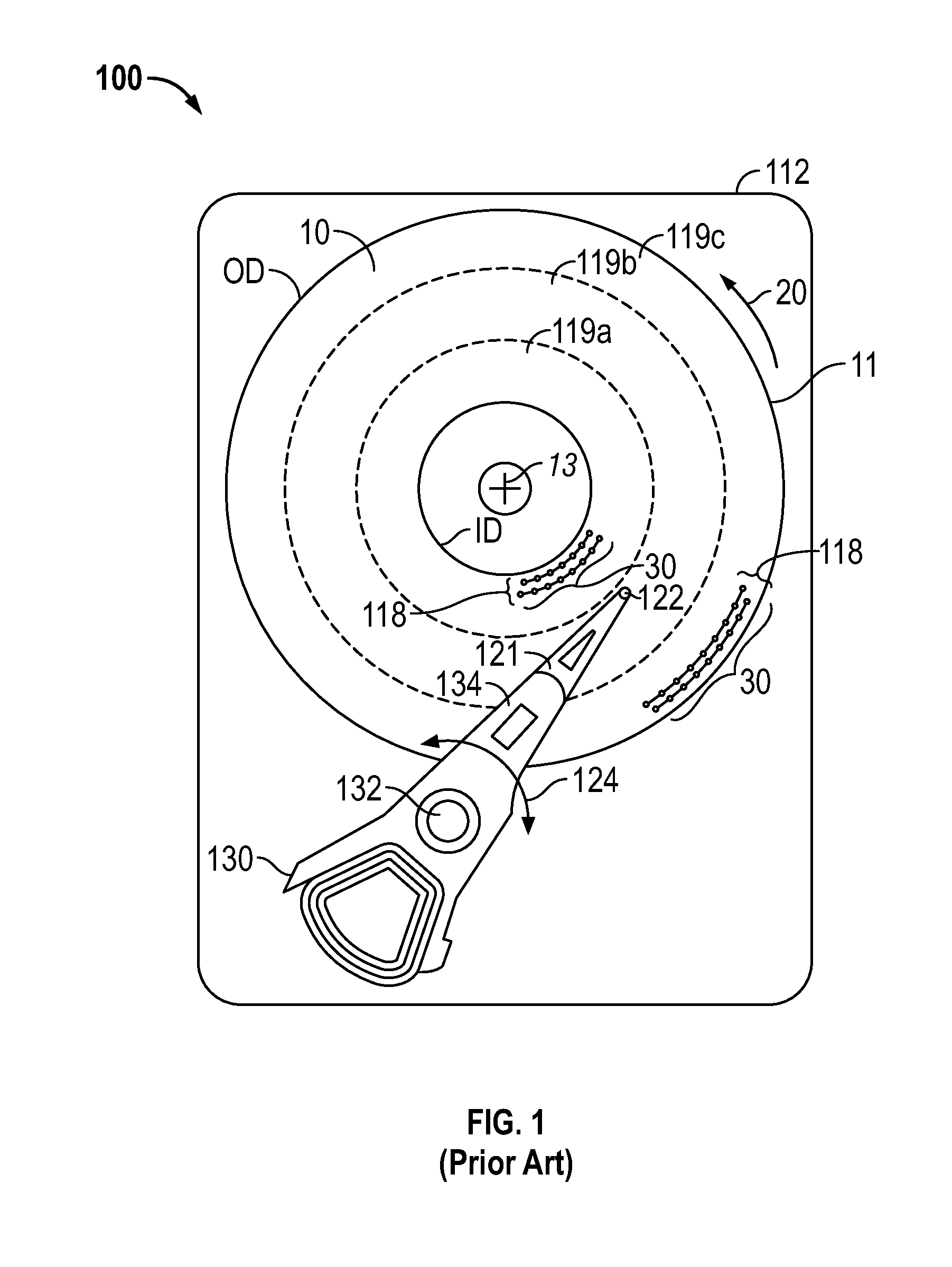
[0030]FIG. 1 is a top view of a disk drive 100 with a patterned magnetic recording disk 10 as described in the prior art. The drive 100 has a housing or base 112 that supports an actuator 130 and a drive motor for rotating the magnetic recording disk 10 about its center 13. The actuator 130 may be a voice coil motor (VCM) rotary actuator that has a rigid arm 134 and rotates about pivot 132 as shown by arrow 124. A head-suspension assembly includes a suspension 121 that has one end attached to the end of actuator arm 134 and a head carrier 122, such as an air-bearing slider, attached to the other end of suspension 121. The suspension 121 permits the head carrier 122 to be maintained very close to the surface of disk 10. A magnetoresistive read head (not shown) and an inductive write head (not shown) are typically formed as an integrated read / write head patterned on the trailing surface of the head carrier 122, as is well known in the art.

[0031]The patterned magnetic recording disk 10...


PUM

PropertyMeasurementUnit
Shapeaaaaaaaaaa
Crosslinkableaaaaaaaaaa
Affinityaaaaaaaaaa

Abstract

A method using directed self-assembly of block copolymers (BCPs) for making an imprint template has the required patterns for both the features in the template's active area and the optically-detectable alignment marks in the template's non-active area. A chemical contrast pattern defined by a lithographic technique forms patterns of lines in both the active area and non-active area, as well as patterns of featureless gap regions in the non-active area. The pattern of lines has the BCP components aligned as lamellae perpendicular to the substrate, while the pattern of featureless gap regions has the BCP components aligned as lamellae parallel to the substrate. The patterns of lines and featureless gap regions in the non-active area define the optically detectable alignment marks. One of the BCP components is removed, leaving the other BCP component as an etch mask to fabricate the imprint template.

Description

BACKGROUND OF THE INVENTION[0001]1. Field of the Invention[0002]This invention relates generally to an imprint template with optically detectable alignment marks, such as a template for imprinting patterned-media magnetic recording disks and semiconductor devices, and to a method for making it using directed self-assembly of block copolymers.[0003]2. Description of the Related Art[0004]Magnetic recording hard disk drives with patterned magnetic recording media have been proposed to increase data density. In patterned media, the magnetic recording layer on the disk is patterned into small isolated data islands arranged in concentric generally circular data tracks. To produce the required magnetic isolation of the patterned data islands, the magnetic moment of spaces between the islands must be destroyed or substantially reduced to render these spaces essentially nonmagnetic. In one type of patterned media, the data islands are elevated regions or pillars that extend above “trenches” ...

Claims


Application Information

Patent Timeline
IPC IPC(8): B29C59/02G03F7/00
CPCG03F7/0035B29C59/022G03F7/0002H01L21/308
Inventor GAO, HEWAN, LEI
Owner WESTERN DIGITAL TECH INC
Why Eureka
Try Eureka