System and Method for Controlling Vapor Compression Systems

a technology of vapor compression system and control system, which is applied in the direction of cooling fluid circulation, lighting and heating apparatus, domestic cooling apparatus, etc., can solve the problems of destabilizing the operation of the entire vapor compression system, and achieve the effect of reducing components costs and efficient operation

Active Publication Date: 2014-10-02
MITSUBISHI ELECTRIC RES LAB INC
View PDF8 Cites 18 Cited by
  • Summary
  • Abstract
  • Description
  • Claims
  • Application Information

AI Technical Summary

Benefits of technology

[0010]Some embodiments of the invention determine the correct amount of refrigerant for an evaporator without using a pressure sensor or without relying on dedicated heat exchanger temperature sensors. For example, one embodiment of the

Problems solved by technology

However, due to variable nature and independent control of the speed of the compressor, that abrupt ch

Method used


Image

  • System and Method for Controlling Vapor Compression Systems
  • System and Method for Controlling Vapor Compression Systems
  • System and Method for Controlling Vapor Compression Systems

Examples


Embodiment Construction

[0025]Various embodiments of the present invention provides a system and a method for controlling an amount of refrigerant in a vapor compression system using a limited number of sensors and processing signals such that stability of the system is maintained and efficiency is optimized. To describe the principles of some embodiments, an exemplar vapor compression system is an air conditioner operating in cooling mode (i.e., removing heat from an indoor environment). However, this example is not meant to limit the scope of the invention, and the various embodiments are intended to cover all operational modes of a vapor compression system (air conditioners operating in cooling and heating modes, chillers, freezers, etc.).

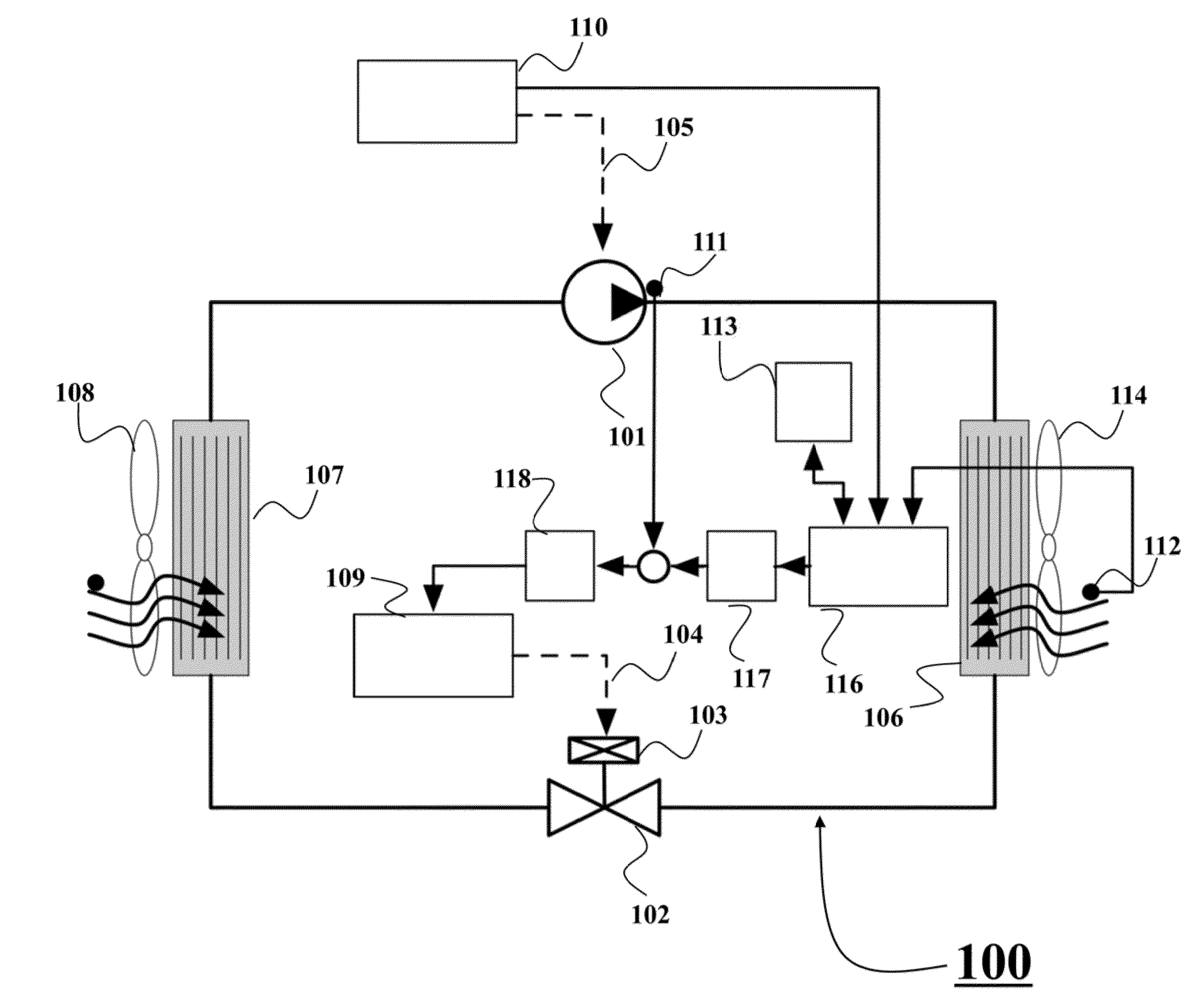
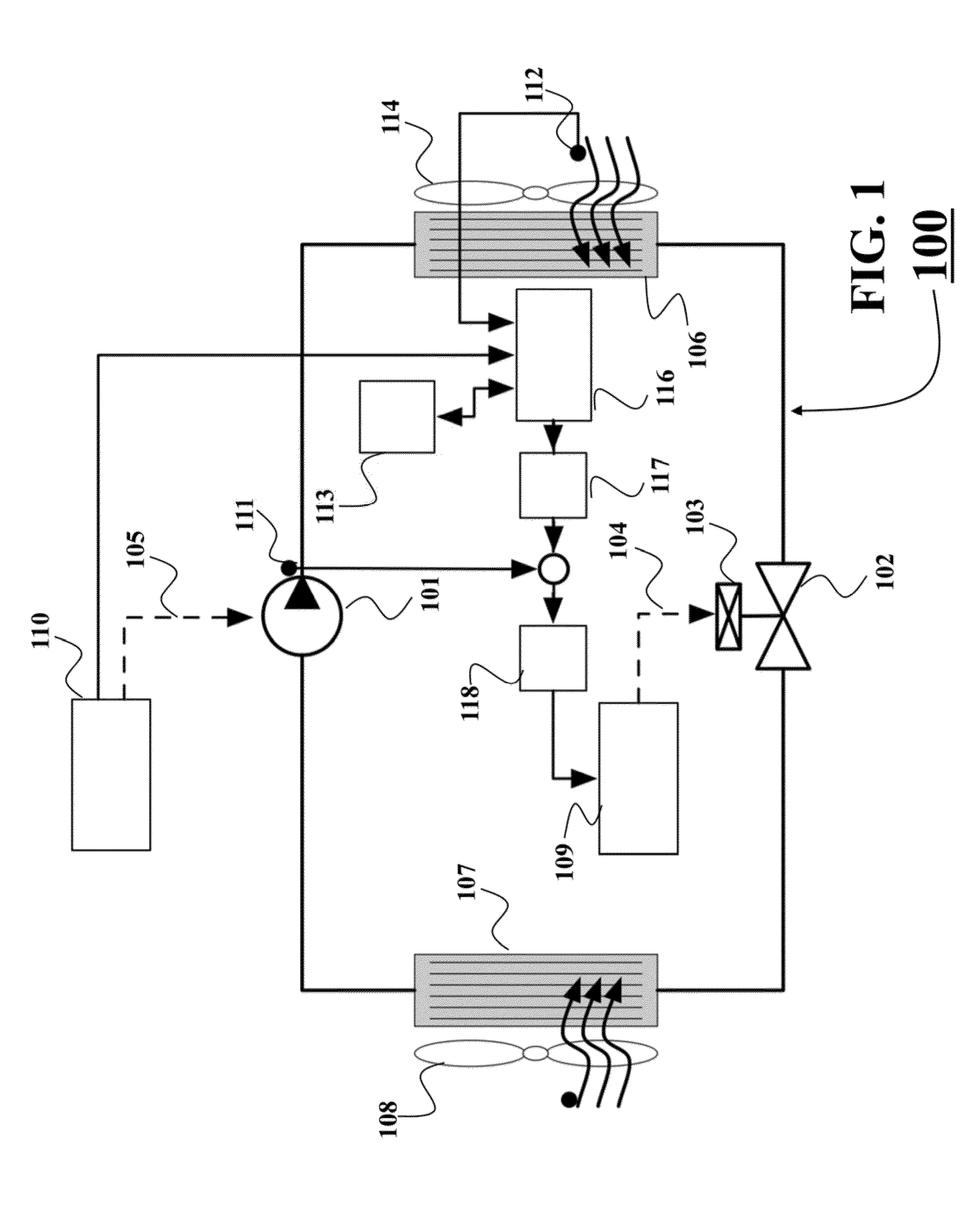
[0026]FIG. 1 shows a block diagram of a vapor compression system 100 according to some embodiments of the invention. An example of the system 100 is any heating, ventilating, and air-conditioning (HVAC) system implementing the vapor compression cycle. Typically, the va...


PUM


Abstract

A method controls a vapor compression system including a variable speed compressor. A desired discharge temperature of the compressor is determined using a mapping between values of the discharge temperature of the compressor and values of speed of the compressor and outdoor air temperature. A transition function for transitioning a current discharge temperature to the desired discharge temperature is determined, such that the transition function is continuous and a rate of change of the transition function is limited. Next, a valve of the vapor compression system is controlled such that the discharge temperature is transitioned to the desired discharge temperature based on the transition function.

Description

FIELD OF THE INVENTION[0001]This invention relates generally to vapor compression systems, and more particularly to controlling operations of the vapor compression system.BACKGROUND OF THE INVENTION[0002]Vapor compression systems, such as heat pumps, refrigeration and air-conditioning systems, are widely used in industrial and residential applications. The vapor compression systems are large consumers of electrical energy and require efficient means cooling and heating. It is desirable to improve the operating efficiency of the vapor compression cycle without increasing costs of the components of the vapor compression systems.[0003]The introduction of variable speed compressors, variable position valves, and variable speed fans to the vapor compression cycle has greatly improved the flexibility of the operation. However, the increased flexibility of these variable-actuators requires careful control of the flow rate of the refrigerant mass. Cooling an environment (for example, a room...

Claims


Application Information

Patent Timeline
IPC IPC(8): F25B49/02
CPCF25B49/02F25B2500/19F25B2600/021F25B2600/2513F25B2700/2106F25B2700/21152Y02B30/70F25B49/022F25B2600/0253
Inventor BURNS, DANLAUGHMAN, CHRISTOPHERBORTOFF, SCOTT A.
Owner MITSUBISHI ELECTRIC RES LAB INC
Why Eureka
Try Eureka