Electrode pattern and touchscreen using the same

Active Publication Date: 2014-10-02
INTERFACE OPTOELECTRONICS SHENZHEN +1
View PDF8 Cites 27 Cited by
  • Summary
  • Abstract
  • Description
  • Claims
  • Application Information

AI Technical Summary

Benefits of technology

The patent invention aims to prevent the moiré effect in touchscreens by creating a pattern of regular and irregular electrodes on the screen. This pattern is designed to overlap with other panel components, which reduces the likelihood of the issues that cause the moiré effect.

Problems solved by technology

While transparent conductors such as ITO may be used for electrodes, however, since the transparent conductive layer has high resistance of 100 ohms / square or more, the sensitivity is lowered when the display device is manufactured in a large scale, and as the size of screen is increased, the cost of the ITO film is rapidly increased.
Accordingly, it is not easy to perform commercialization thereof.
However, when the electrode pattern of the touch panel is formed in the mesh structure having regular and constant intervals, there is a problem in that period characteristics of the metal mesh electrode pattern of the touch panel may cause interference with a periodic pixel pattern of the IC circuit or a regular pattern structure of another optical film, such as a black matrix pattern of a color filter included in an image display device overlapped with each other, thereby causing a so-called “moiré” phenomenon.
The occurrence of moiré makes it difficult to see a displayed image of the display, and thereby deteriorates the visual operability or usability of the touch screen device.
In particular, low-frequency moiré will make the display difficult to be viewed.

Method used


Image

  • Electrode pattern and touchscreen using the same
  • Electrode pattern and touchscreen using the same
  • Electrode pattern and touchscreen using the same

Examples


Embodiment Construction

[0024]In the following detailed description of the present invention, reference is made to the accompanying drawings which form a part hereof and is shown by way of illustration and specific embodiments in which the invention may be practiced. These embodiments are described in sufficient details to enable those skilled in the art to practice the invention. Other embodiments may be utilized and structural, logical, and electrical changes may be made without departing from the scope of the present invention. The following detailed description, therefore, is not to be taken in a limiting sense, and the scope of the present invention is defined by the appended claims.

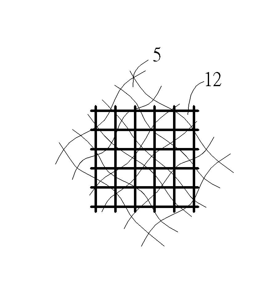
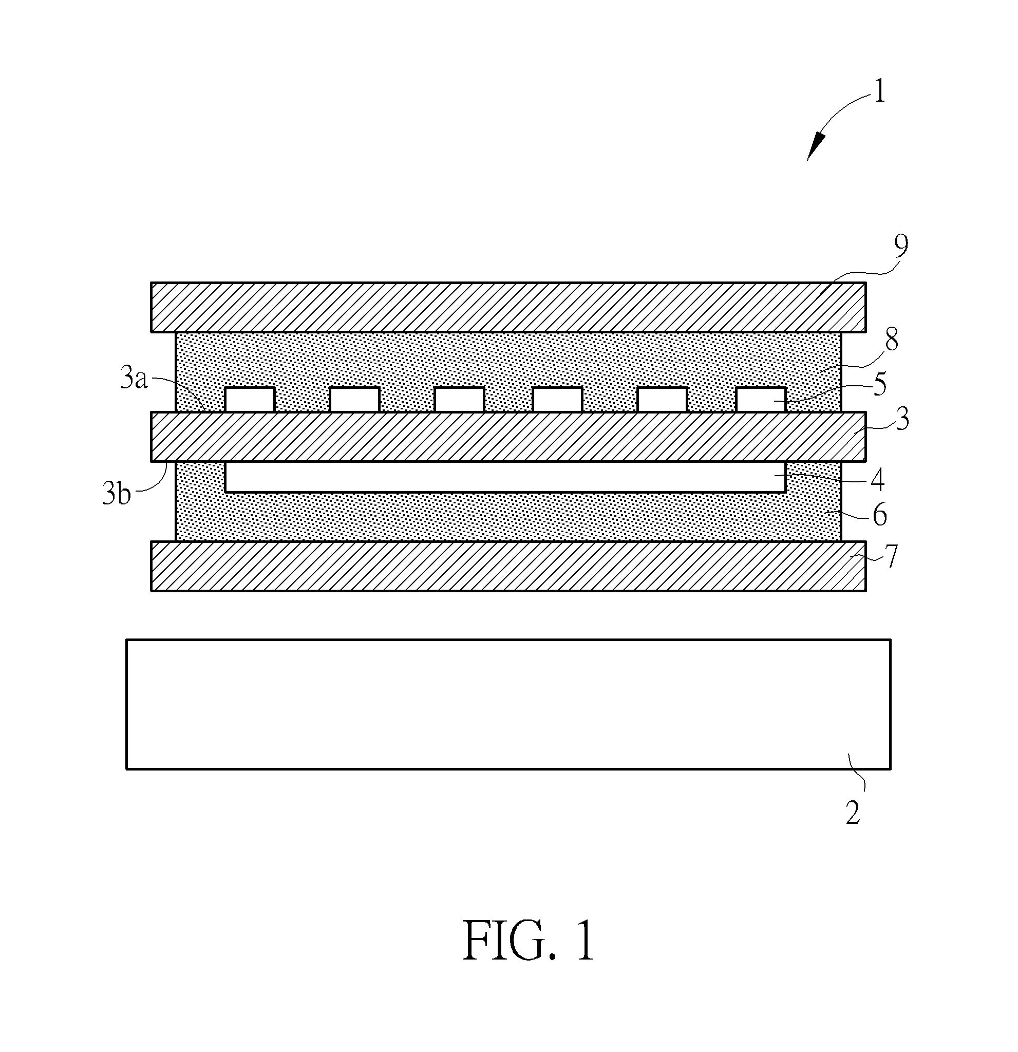
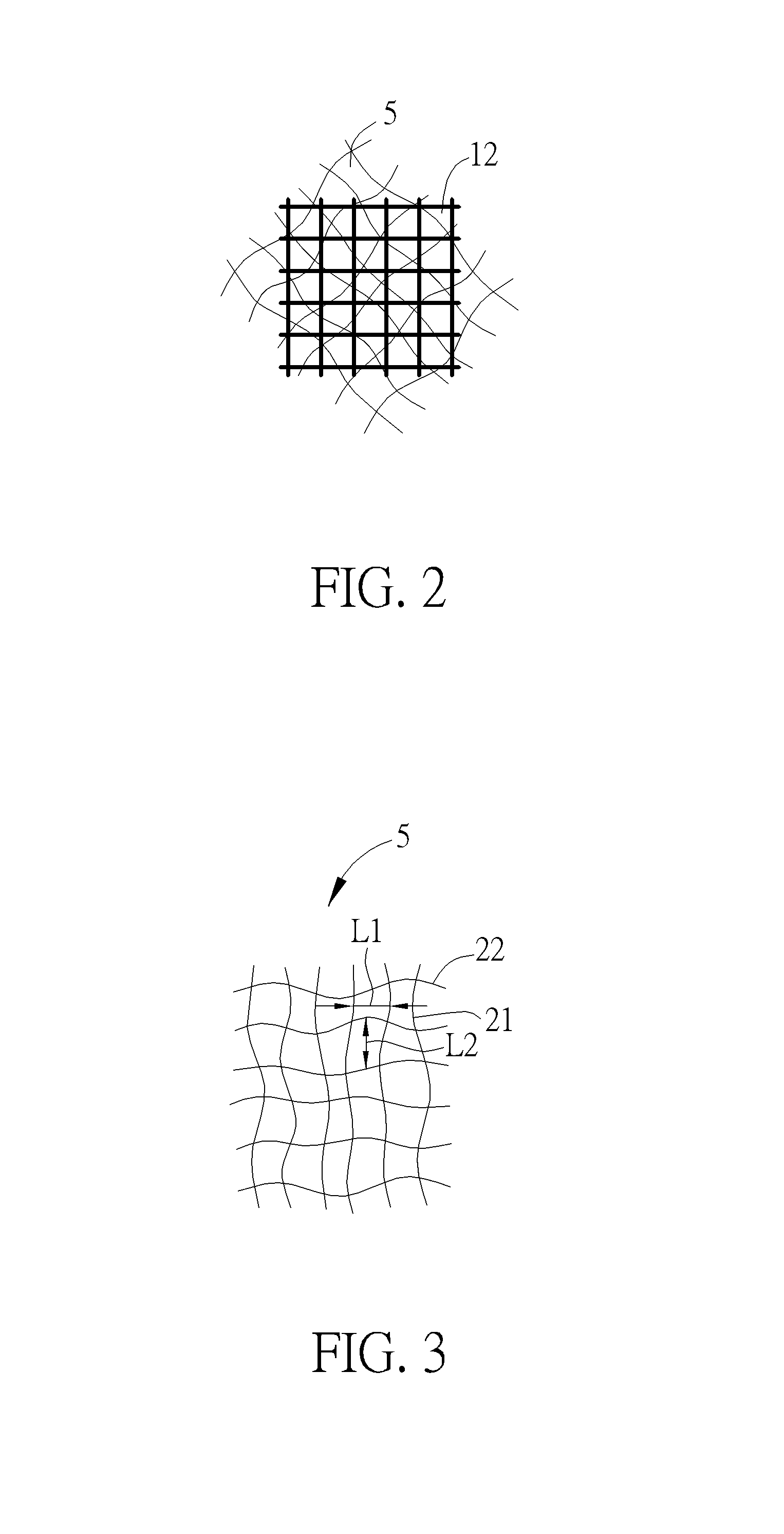
[0025]FIG. 1 illustrates an exemplary touch position-sensing panel 1 which overlies a display 2. In the illustrated example, the panel 1 includes an insulating substrate 3 having two opposing faces 3a and 3b. Although touch sensors may implement other types of touch sensing, for discussion purposes, the drawing shows an ex...


PUM


Abstract

A touchscreen electrode pattern constituted by wavy conductive lines, each wavy conductive line includes multiple troughs of wave and multiple crests of waves, wherein an interval between adjacent troughs of waves in each wavy conductive line is larger than 1.5 times of a predetermined value, and an amplitude difference between adjacent trough of waves and crest of waves in each wavy conductive line is smaller than ⅓ times of the predetermined value.

Description

BACKGROUND OF THE INVENTION[0001]1. Field of the Invention[0002]The present invention generally relates to a touchscreen, and more particularly, to a touchscreen with a mesh-like electrode pattern which is capable of eliminating the moiré phenomenon.[0003]2. Description of the Prior Art[0004]Touchscreen displays are able to detect a touch within the active or display area, such as detecting whether a finger is present pressing a fixed-image touchscreen button or detecting the presence and position of a finger on a larger touchscreen display. Some touchscreens can also detect the presence of elements other than a finger, such as a stylus used to generate a digital signature, select objects, or perform other functions on a touchscreen display.[0005]The Use of a touchscreen as part of a display allows an electronic device to change a display image, and to present different buttons, images, or other regions that can be selected, manipulated, or actuated by touch. Touchscreens can theref...

Claims


Application Information

Patent Timeline
IPC IPC(8): H05K1/02
CPCH05K1/0296G06F3/0412G06F3/0445G06F2203/04112H05K1/0287H05K2201/0108H05K2201/09681
Inventor HUANG, KUNG-CHIEH
Owner INTERFACE OPTOELECTRONICS SHENZHEN
Why Eureka
Try Eureka