Transformable Adaptive Gripper System

Inactive Publication Date: 2014-10-02
FRAUNHOFER GESELLSCHAFT ZUR FOERDERUNG DER ANGEWANDTEN FORSCHUNG EV
View PDF9 Cites 11 Cited by
  • Summary
  • Abstract
  • Description
  • Claims
  • Application Information

AI Technical Summary

Benefits of technology

[0013]As is described in even more detail below, the end effector according to the invention makes it possible to copy the surface contour of the depositing surface of a mold or else the surface contour of a component or semi-finished product in the flexible container by the flexible container being pressed against the depositing surface or the component (i.e. filler in a flowable or plastically or elastically deformable state), and subsequently “to freeze” the surface contour copied in the flexible container (transfer the filler into the rigid or dimensionally stable state). Subsequently, for example, an object gripped with gripper elements, such as, for example, a textile fabric or a prepreg, can be deposited as exactly as possible on the depositing surface of the mold. If the end effector is intended to be used at a later time for a new depositing surface having a different surface contour, the filler can be transferred again into a flowable or elastically or plastically deformable state in order to copy the new surface contour, followed by the “freezing” of the copied surface contour by the filler being switched again into the solidified state. After the “freezing” of the surface contour of a component or semi-finished product, the end effector can also be used to regulate the temperature of the component or semi-finished product as uniformly as possible, for example by means of heating elements which are attached on the surface of the flexible container.
[0051]By means of this modular construction, different bases can be plugged together under constant control of the end effector and can thus be adapted in a simple manner to different sizes of semi-finished product and / or component.
[0062]The spacer fabric preferably affords a certain degree of compression resistance. As a result, the molding accuracy is maintained. By applying a negative pressure or vacuum to the spacer fabric, a suction is produced over the entire, slightly porous or air-permeable surface of the spacer fabric, the suction securing the semi-finished product and / or component to be gripped. The compression resistance of the spacer fabric in turn ensures that the airflow in the interior of the spacer fabric is uniform and that there are no regions at which the suction effect is lost.

Problems solved by technology

However, this only functions in the case of simple geometries.
This is a problem specifically in the case of the small batch sizes customary in the CFRP area, since additional investment and development is thus required at the beginning of production of new components.

Method used


Image

  • Transformable Adaptive Gripper System
  • Transformable Adaptive Gripper System
  • Transformable Adaptive Gripper System

Examples


Embodiment Construction

[0009]Taking into consideration what has been stated above, it is an object of the present invention to provide an end effector which can be used for differently shaped semi-finished products or components and can, for example, efficiently grip said semi- finished products / components and deposit the latter in a precisely fitting manner in a mould or also can uniformly regulate the temperature of or compact said semi-finished products / components. It is a further object of the present invention to provide a suitable method using the end effector according to the invention.

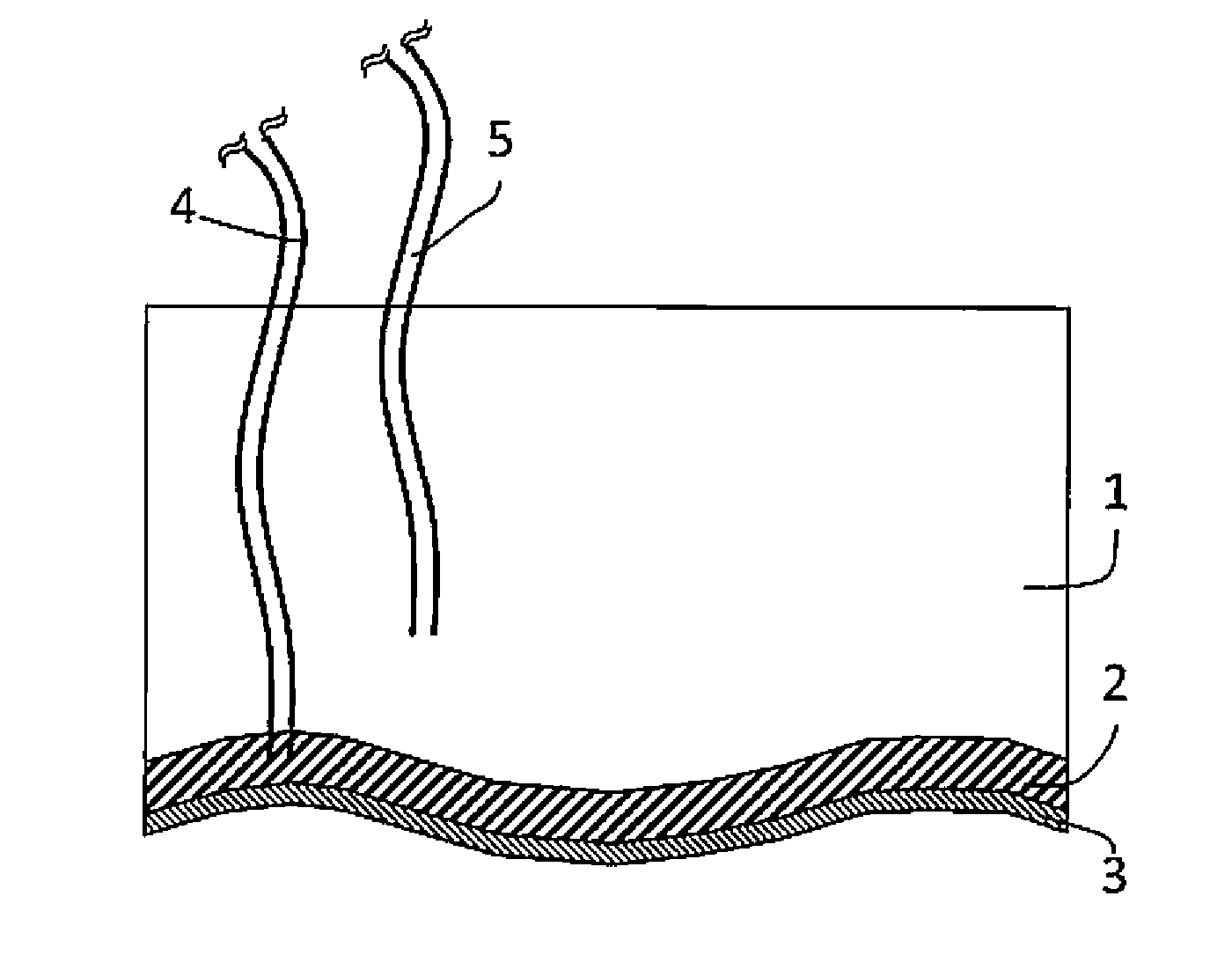
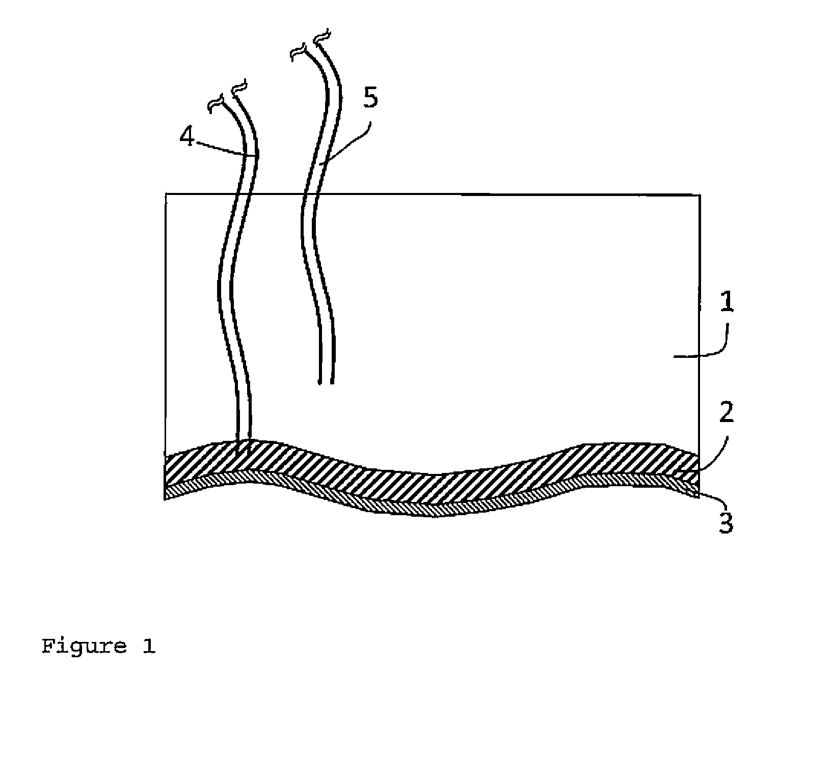
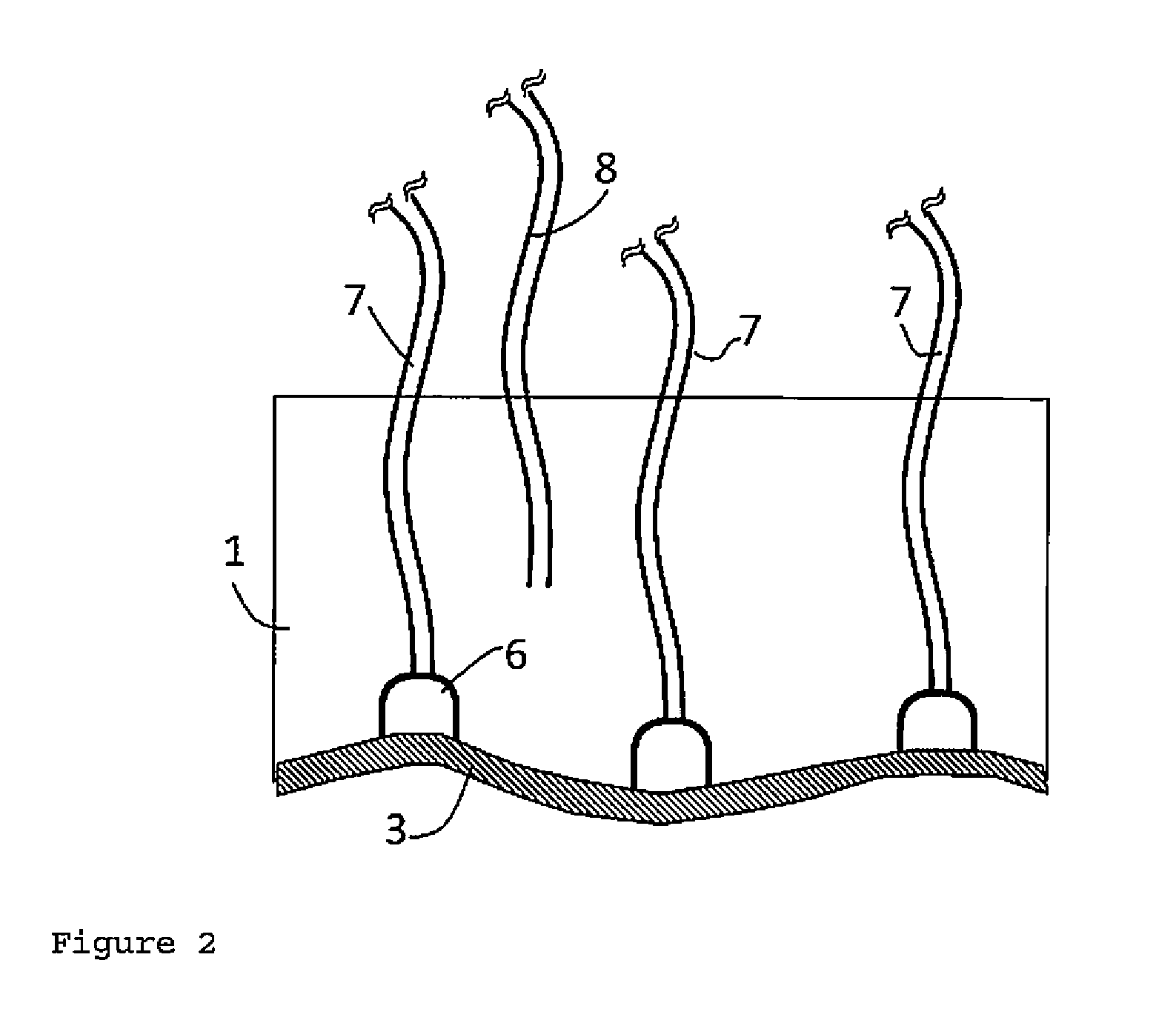
[0010]According to a first aspect of the present invention, the object is achieved by providing an end effector, comprising[0011]a flexible container which contains a filler, wherein the filler is switchable between a flowable or deformable state and a rigid or dimensionally stable state, and[0012]one or more working elements for gripping, temperature regulation and / or compaction.

[0013]As is described in even more de...


PUM


Abstract

An end effector that includes: a flexible container which contains a filler, wherein the filler is switchable between a flowable or deformable state and a rigid or dimensionally stable state, and one or more working elements for gripping, temperature regulation and / or compaction.

Description

BACKGROUND OF THE INVENTION[0001]Fiber-reinforced plastics are already established in many technical areas, including as a lightweight construction material which can save weight of an order of magnitude of 30% in comparison to the classic metal construction. CFRP (carbon-fiber-reinforced plastic) is widely used specifically in the air travel area. A substantial reason which prevents even greater use resides in the production costs which are still comparatively high. These, in turn, are caused by a not insignificant proportion of manual working steps which have not yet been automated in the “handling” of the fibers(cutting out, preforming, deforming, draping).[0002]At present, various approaches are known for automating the handling of fibers. Examples in this context include the following approaches:[0003]fiber patch preforming (disadvantage: very low depositing rates).[0004]Robot-assisted depositing of multi-axial fabric (MAF) and other large-area semi-finished products at higher ...

Claims


Application Information

Patent Timeline
Patent Type & Authority Applications(United States)
IPC IPC(8): B25J15/00
CPCB25J15/0023B25J15/0076B25J15/0071B25J15/00B25J15/06
Inventor GRAUPNER, ROBERTDRECHSLER, KLAUSSCHMITT, STEFANWOLLING, JAKOB
Owner FRAUNHOFER GESELLSCHAFT ZUR FOERDERUNG DER ANGEWANDTEN FORSCHUNG EV
Why Eureka
Try Eureka