Non-contact magnetic measuring element

A measuring element, non-contact technology, applied in the direction of linear/angular velocity measurement, measuring device, velocity/acceleration/impact measurement, etc., can solve the problem of difficulty in precise control of the speed of the fan blade, and achieve the goal of ensuring the hatching rate and consistency. Effect

Inactive Publication Date: 2011-05-04
蚌埠市双利电器有限责任公司
View PDF4 Cites 0 Cited by
  • Summary
  • Abstract
  • Description
  • Claims
  • Application Information

AI Technical Summary

Problems solved by technology

However, in the prior art, there is no system or device that can accurately measure the speed of the fan blade, and it is difficult to accurately control the speed of the fan blade

Method used


Image

  • Non-contact magnetic measuring element
  • Non-contact magnetic measuring element

Examples


Embodiment Construction

[0008] In order to make it easy to understand the technical means, creation features, achieved goals and effects of the present invention, the present invention will be further described below with reference to the specific figures.

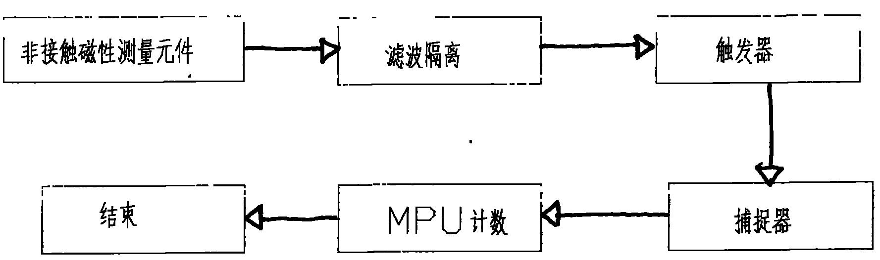
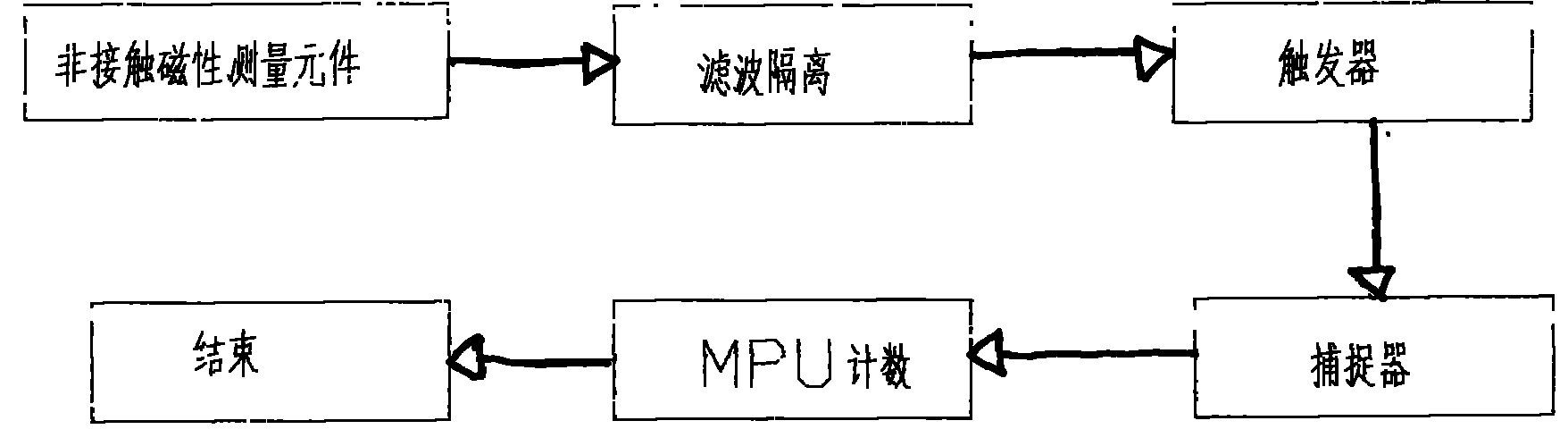
[0009] like figure 1 As shown, a non-contact magnetic measurement element, the method is: through the non-contact magnetic measurement element to measure the pulse electrical signal formed by the operation of the fan blade, after filtering and isolation, then through the trigger and catcher, and finally input to the MPU system for counting, Obtain the fan speed value.

[0010] The basic principles and main features of the present invention and the advantages of the present invention have been shown and described above. Those skilled in the art should understand that the present invention is not limited by the above-mentioned embodiments, and the descriptions in the above-mentioned embodiments and the description are only to illustrate the princi...


PUM


Abstract

The invention discloses a non-contact magnetic measuring element, which relates to a detection control system. The technical scheme of the non-contact magnetic measuring element is as follows: the non-contact magnetic measuring element measures electrical pulse signals formed by the running of a fan blade; then the electrical pulse signals are subject to filtering isolation and pass through a trigger and a catcher; and finally, the processed electrical pulse signals are output to an MPU (micro processing unit) system to count, thereby obtaining the revolving speed value of the fan blade. The non-contact magnetic measuring element provided by the invention has the beneficial effects that because of adopting the technical scheme, the measuring element can measure the revolving speed value of the fan blade, and control the uniformity of a temperature field, thereby guaranteeing the consistency of temperatures of hatching eggs and the birth rate of the hatching eggs.

Description

technical field [0001] The invention relates to a detection control system, in particular to a non-contact magnetic measuring element. Background technique [0002] In the fields of incubation equipment, chemical industry, biopharmaceutical and environmental control, various parameter detection systems are usually installed to measure parameters such as temperature, humidity, air pressure and wind speed, so as to facilitate the operation of the equipment. The control method of the temperature field in the existing incubator is to install a plurality of heating pipes and fans in the incubator housing, install the heating pipes in the middle or rear of the housing, and install the fans vertically in the center of the housing or in a The upper part of the vertical side plate is stirred and blown by a fan to make the hot air circulate in the incubator. Therefore, the parameters of the wind field in the incubator are extremely important. It has a great influence on the uniformit...

Claims


Application Information

Patent Timeline
Patent Type & Authority Applications(China)
IPC IPC(8): G01P3/481
Inventor 马传武
Owner 蚌埠市双利电器有限责任公司
Why Eureka
Try Eureka