Inverted microscope system

a microscope system and microscope technology, applied in the field of inverted microscope systems, can solve the problem that the propagation phenomenon cannot be observed in the optical system of total internal reflection fluorescence microscopy, and achieve the effect of reducing the number of optical systems

Active Publication Date: 2014-10-02
EVIDENT CORP
View PDF6 Cites 6 Cited by
  • Summary
  • Abstract
  • Description
  • Claims
  • Application Information

AI Technical Summary

Problems solved by technology

Thus, the phenomenon of the propagation cannot be observed in the total internal reflection fluorescence microscopy optical system.

Method used


Image

  • Inverted microscope system
  • Inverted microscope system
  • Inverted microscope system

Examples


Embodiment Construction

[0023]Exemplary embodiments of the invention will be described below in detail with reference to the appended drawings. Note that the invention is not limited to the embodiments. Furthermore, each of the drawings to be referred to in the description merely schematically illustrates the shapes, sizes, and positional relationships of the components to the extent that the contents of the invention can be understood. In other words, the invention is not limited to the shapes, sizes, and positional relationships illustrated as examples in each of the drawings.

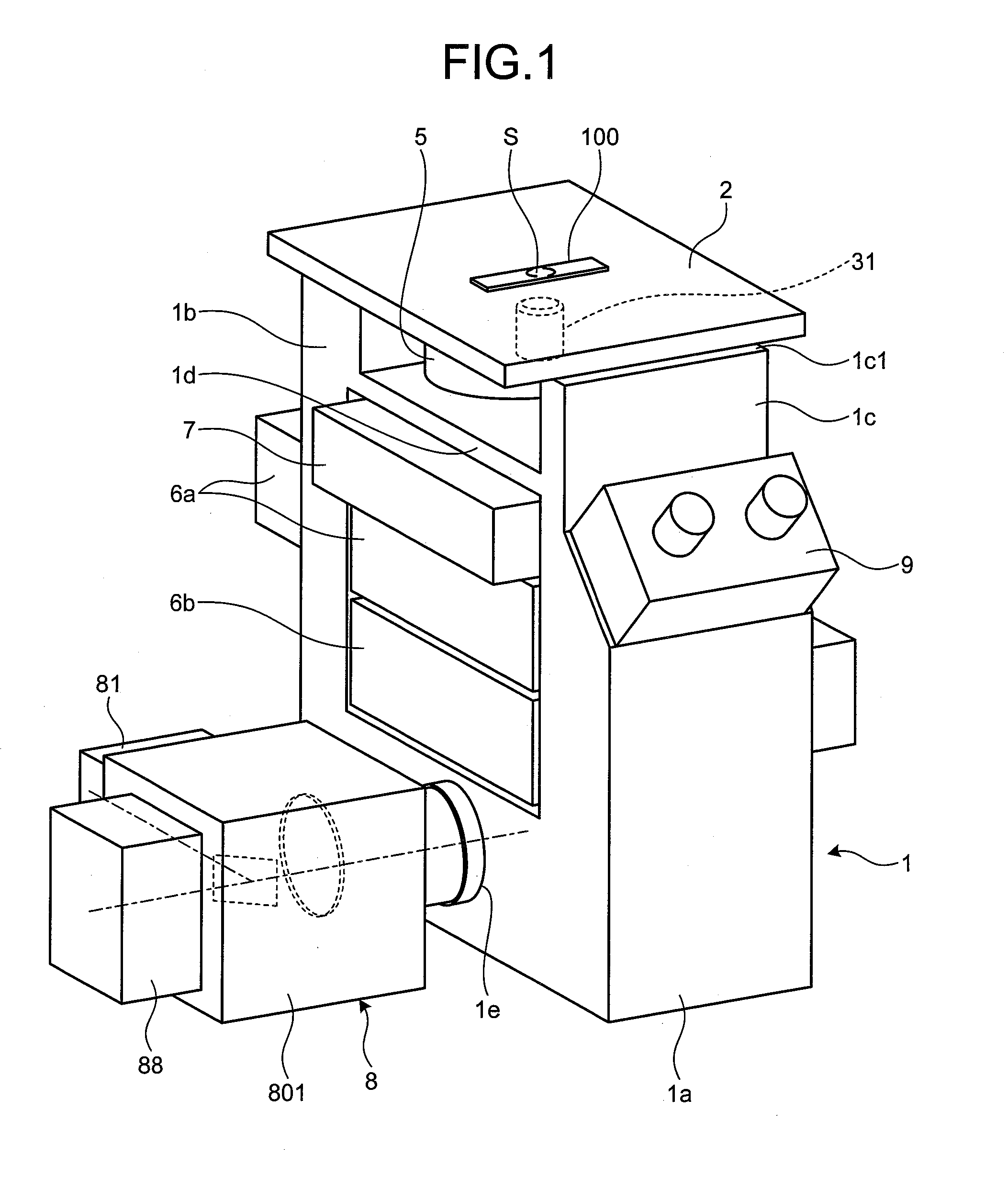
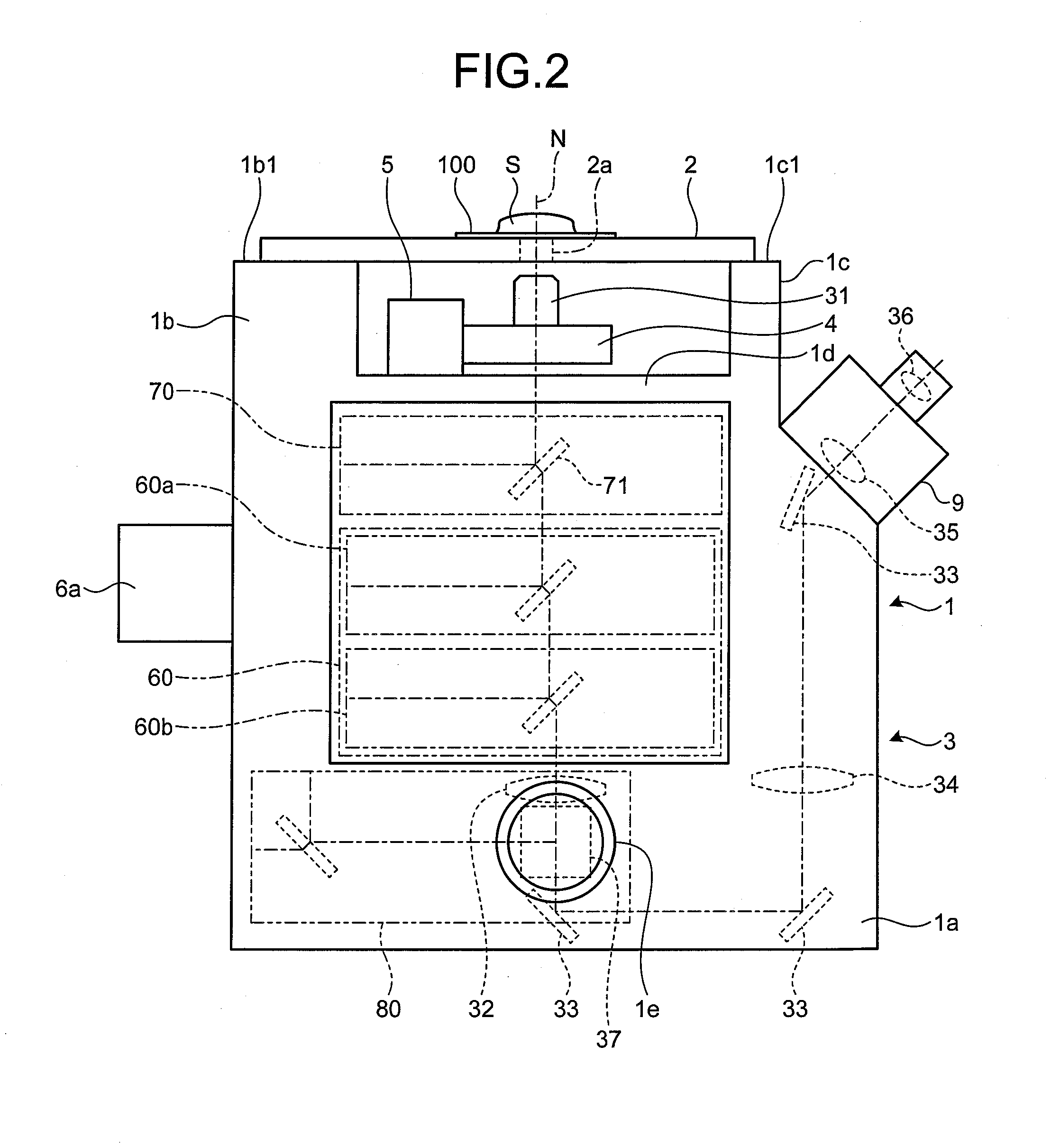
[0024]First, an inverted microscope system according to some embodiments of the invention will be described with reference to the drawings. FIG. 1 is a schematic diagram of the whole configuration of the inverted microscope system according to some embodiments. FIG. 2 is a side view of the internal configuration of the inverted microscope system illustrated in FIG. 1.

[0025]The inverted microscope system is configured to observe a sp...


PUM


Abstract

An inverted microscope system includes an objective lens holding unit that holds an objective lens configured to collect at least observation light from a specimen, a tube lens configured to form an image using the observation light collected by the objective lens, a total internal reflection fluorescence microscopy optical system provided between the objective lens and the tube lens and configured to observe the observation light from the specimen using a total reflection illumination, and a disk scanning confocal optical system including a rotary disk on which a confocal opening is formed, the confocal opening being placed at a position substantially conjugate to a focus position of the objective lens. A relative distance between the focus position of the objective lens and the substantially conjugate position is changeable along an optical path of the observation light.

Description

CROSS-REFERENCE TO RELATED APPLICATIONS[0001]This application is based upon and claims the benefit of priority from Japanese Patent Application No. 2013-072213, filed on Mar. 29, 2013, the entire contents of which are incorporated herein by reference.BACKGROUND[0002]1. Technical Field[0003]The disclosure relates to an inverted microscope system that irradiates a specimen with illumination light to observe the specimen by receiving the light reflected from the specimen.[0004]2. Related Art[0005]A microscope that illuminates a specimen to observe the specimen has conventionally been used for observing, for example, a cell in the field of medicine, biology, or the like. Furthermore, in the industrial field, a microscope system is used for various purposes such as the quality management of a metal structure, the research development of new materials, or the inspection of electronic devices or magnetic heads.[0006]Examples of an optical system used for observing fluorescence from a speci...

Claims


Application Information

Patent Timeline
Patent Type & Authority Applications(United States)
IPC IPC(8): G02B21/00
CPCG02B21/0076G02B21/0044G01N21/648G02B21/0088
Inventor AMANO, YUSUKEKARASAWA, MASAYOSHI
Owner EVIDENT CORP
Why Eureka
Try Eureka