Optical module and optical transceiver module

Active Publication Date: 2014-10-02
DELTA ELECTRONICS INC
View PDF22 Cites 5 Cited by
  • Summary
  • Abstract
  • Description
  • Claims
  • Application Information

AI Technical Summary

Benefits of technology

The present invention provides an optical module and an optical transceiver module that have a simple structure and are easy to manufacture. The optical module includes a first light-guide element, an optical element, a first optical fiber, and a beam splitter. The beam splitter is attached to the first light-guide element and partially reflects and partially transmits a light beam. The optical transceiver module further includes a second light-guide element, a second optical fiber, and a light receiving element. The optical module and the optical transceiver module have a high optical coupling efficiency and can be used for transmitting and receiving light beams.

Problems solved by technology

However, laser diode with TO can package is just perpendicularly disposed on a circuit board, such that optical coupled difficulty is increase when coupling a light beam emitted from the laser diode into an optical fiber, and partially light beam lost when coupling the light beam into the laser diode.
Besides, the TO can package is usually made of metallic material, such that the manufacturing cost is expansive and the volume cannot be effectively minimized.

Method used


Image

  • Optical module and optical transceiver module
  • Optical module and optical transceiver module
  • Optical module and optical transceiver module

Examples


Embodiment Construction

[0030]A preferred embodiment of the present invention will be described with reference to the drawings.

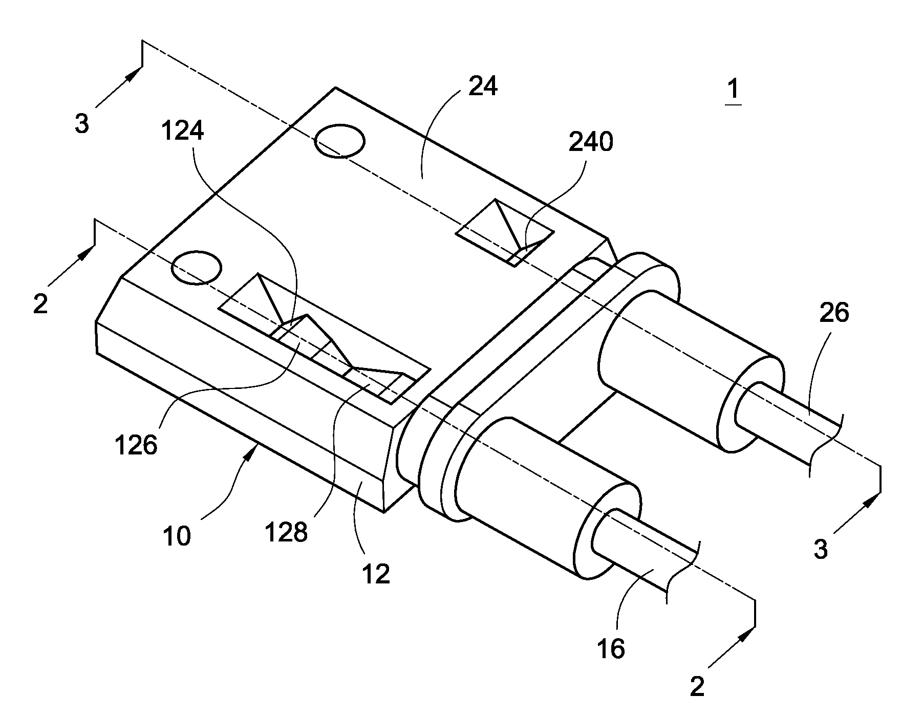
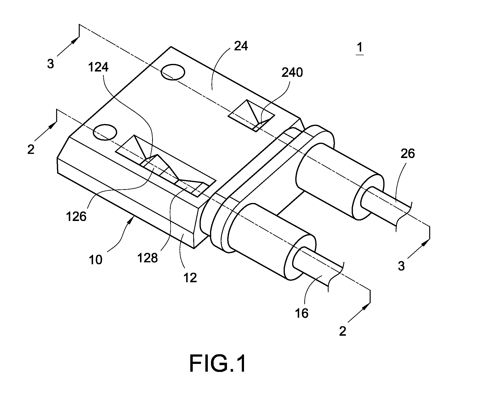
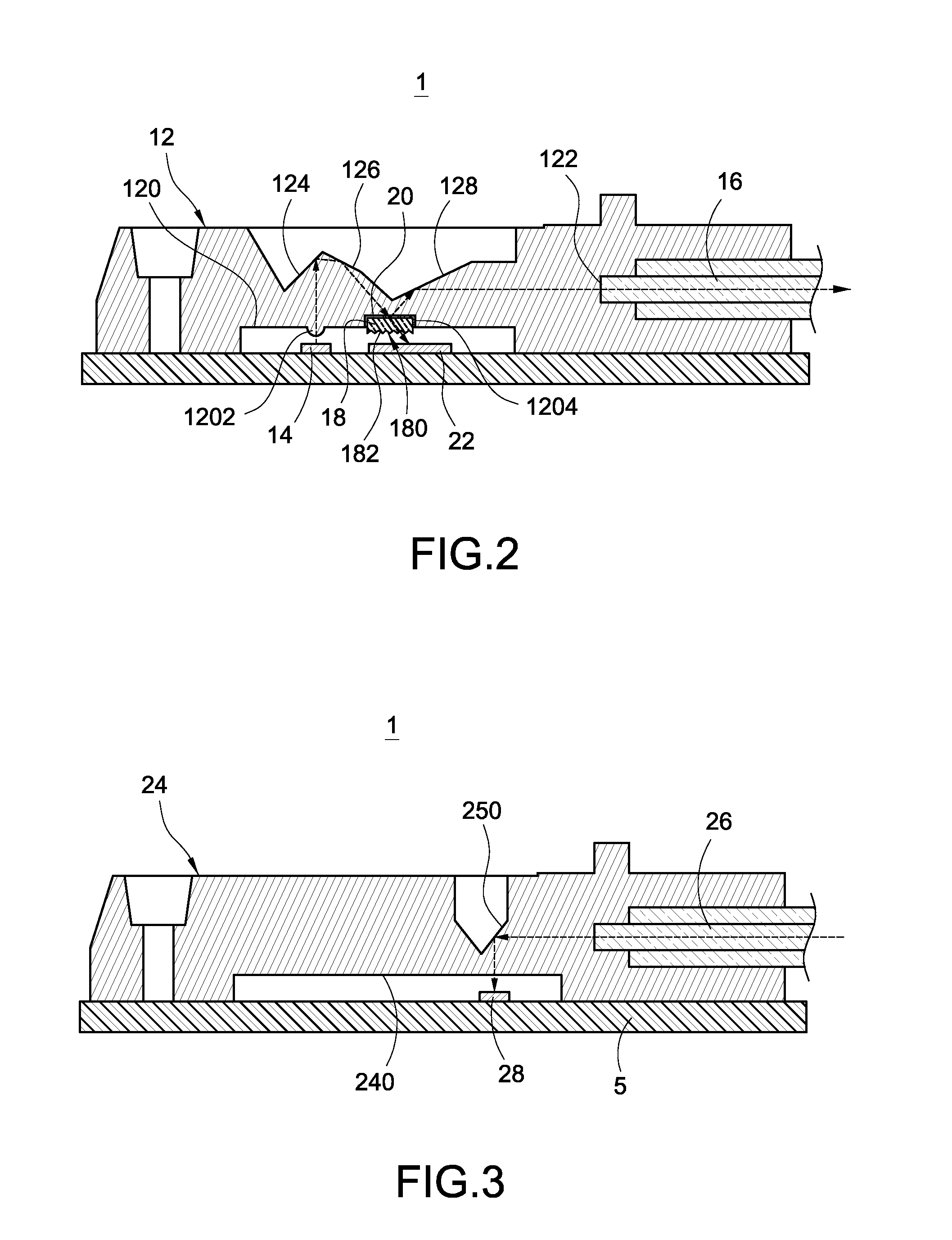
[0031]Referred is made to FIG. 1 and FIG. 2, FIG. 1 is a perspective view of an optical transceiver module according to the present invention, and FIG. 2 is a sectional view of the optical transceiver module on line 2-2 shown on FIG. 1. The optical transceiver module 1 includes an optical module 10. The optical module 10 includes a first light-guide element 12, an optical element 14, a first optical fiber 16, and a beam splitter 18.

[0032]A refractive index of the first light-guide element 12 is preferably between 1.12 and 2.08. The first light-guide element 12 includes a first surface 120 faced to a first direction and a second surface 122 faced to a second direction different from the first direction. The first direction is different from the second direction. The first surface 120 includes a protrusive portion 1202 and a recess 1204 formed thereon.

[0033]The first light-guide elem...


PUM


Abstract

An optical module includes a first light-guide element, an optical element, a first optical fiber, and a beam splitter. The first light-guide element includes a first surface and a second surface. The optical element corresponds to the first surface. The first optical fiber is contacted with the second surface. The beam splitter is attached to the first surface, the beam splitter partially reflects and partially transmits a light beam striking thereon. A refractive index of the beam splitter is different from a refractive index of the first light-guide element.

Description

BACKGROUND OF THE INVENTION[0001]1. Field of the Invention[0002]The present invention relates to an optical module and an optical transceiver module, and in particular to an optical module and an optical transceiver using[0003]2. Description of Related Art[0004]Fiber-optic communication is a way for transmitting information by using light and optical fiber, which is belonging to a wire communication and has advantages of high transmission capacity and safety, and is progressively becoming a main wire communication way.[0005]In the past, laser diode with transistor outline can (TO can) package is widely used in optical fiber communication. However, laser diode with TO can package is just perpendicularly disposed on a circuit board, such that optical coupled difficulty is increase when coupling a light beam emitted from the laser diode into an optical fiber, and partially light beam lost when coupling the light beam into the laser diode.[0006]Besides, the TO can package is usually mad...

Claims


Application Information

Patent Timeline
IPC IPC(8): H04B10/40
CPCH04B10/40G02B6/4214G02B6/4246G02B6/4255G02B6/4286G02B6/02G02B6/42
Inventor LIAO, YU-HSIENHUANG, MING-YIYANG, TE-HSUAN
Owner DELTA ELECTRONICS INC
Why Eureka
Try Eureka