Exhaust emission purification control device for engine

a technology of exhaust gas and purification control, which is applied in the direction of electrical control, process and machine control, instruments, etc., can solve the problems of unfavorable osub>2 /sub>feedback control, unburnt gas remaining in the exhaust gas, and liable to be exhausted to the downstream of the catalys

Active Publication Date: 2014-10-02
HONDA MOTOR CO LTD
View PDF6 Cites 3 Cited by
  • Summary
  • Abstract
  • Description
  • Claims
  • Application Information

AI Technical Summary

Benefits of technology

[0014]With these problems understood, it is an object of an embodiment of the present invention to provide an exhaust emission purification control device for an engine that accurately estimates the accumulated oxygen amount of the catalyst during the termination of the reduction treatment using a simple method.

Problems solved by technology

However, excessively rich fuel may cause unburnt gas remaining in the exhaust gas after the catalyst.
In the past, there is a problem with respect to setting of the control, setting a table for the subtraction counter, and similar settings that are laborious.
This does not allow an ordinary O2 feedback control.
However, if an excessively rich air-fuel ratio is provided for the oxidation capacity of the catalyst at that time point, unburnt gas is liable to be exhausted to the downstream of the catalyst.
A problem is that in order to have an early termination of the reduction treatment, this margin is required to be omitted to the extent possible.
Accordingly, an excessive correction to the rich side may occur.

Method used


Image

  • Exhaust emission purification control device for engine
  • Exhaust emission purification control device for engine
  • Exhaust emission purification control device for engine

Examples


Embodiment Construction

[0045]Hereinafter, a description will be given of an exemplary embodiment where an exhaust emission purification control device for an engine according to the present invention is applied to, for example, a motorcycle by referring to FIGS. 1 to 7.

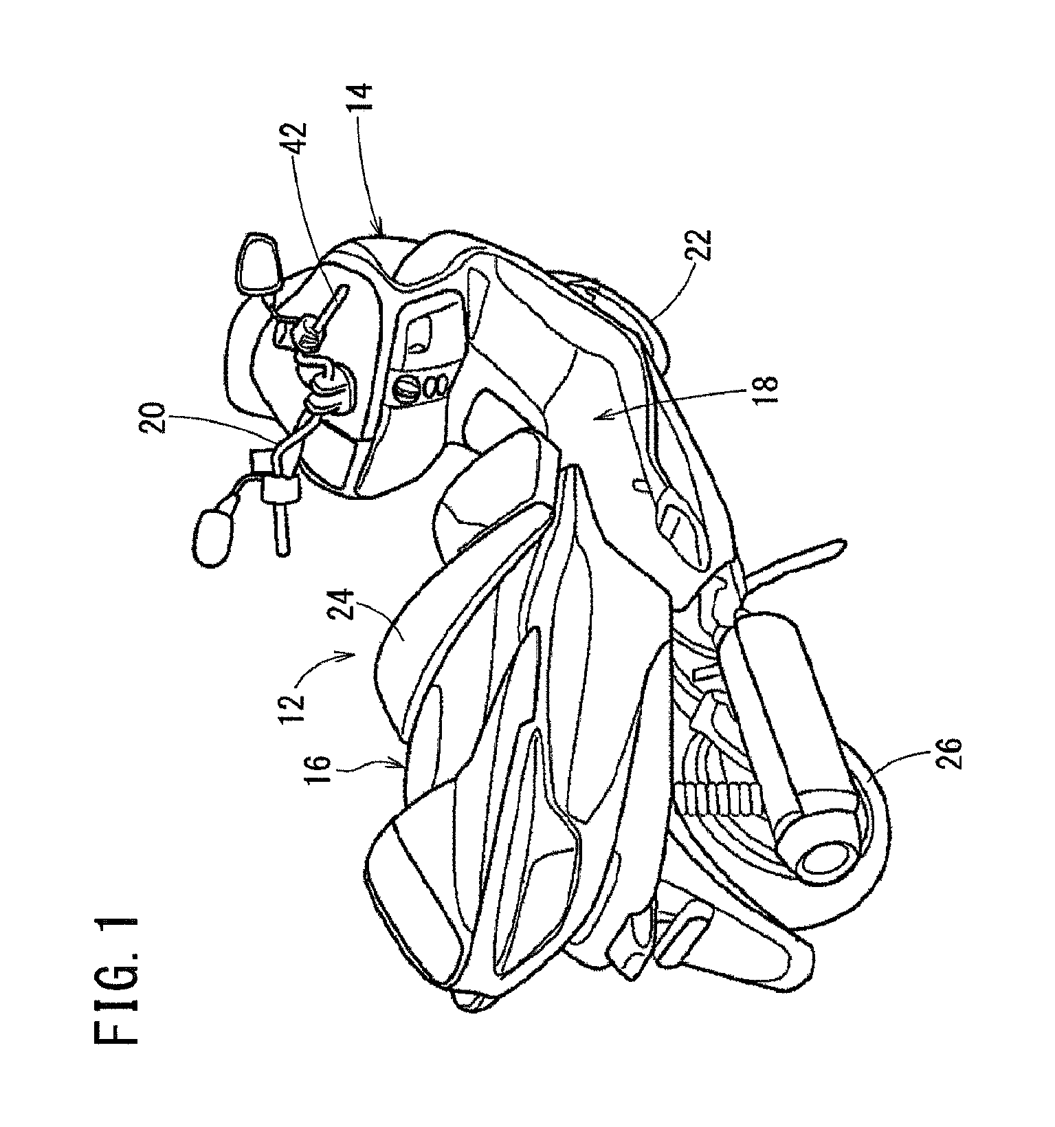
[0046]First, a description will be given of a motorcycle 12 with an exhaust emission purification control device 10 for an engine according to this embodiment by referring to FIG. 1.

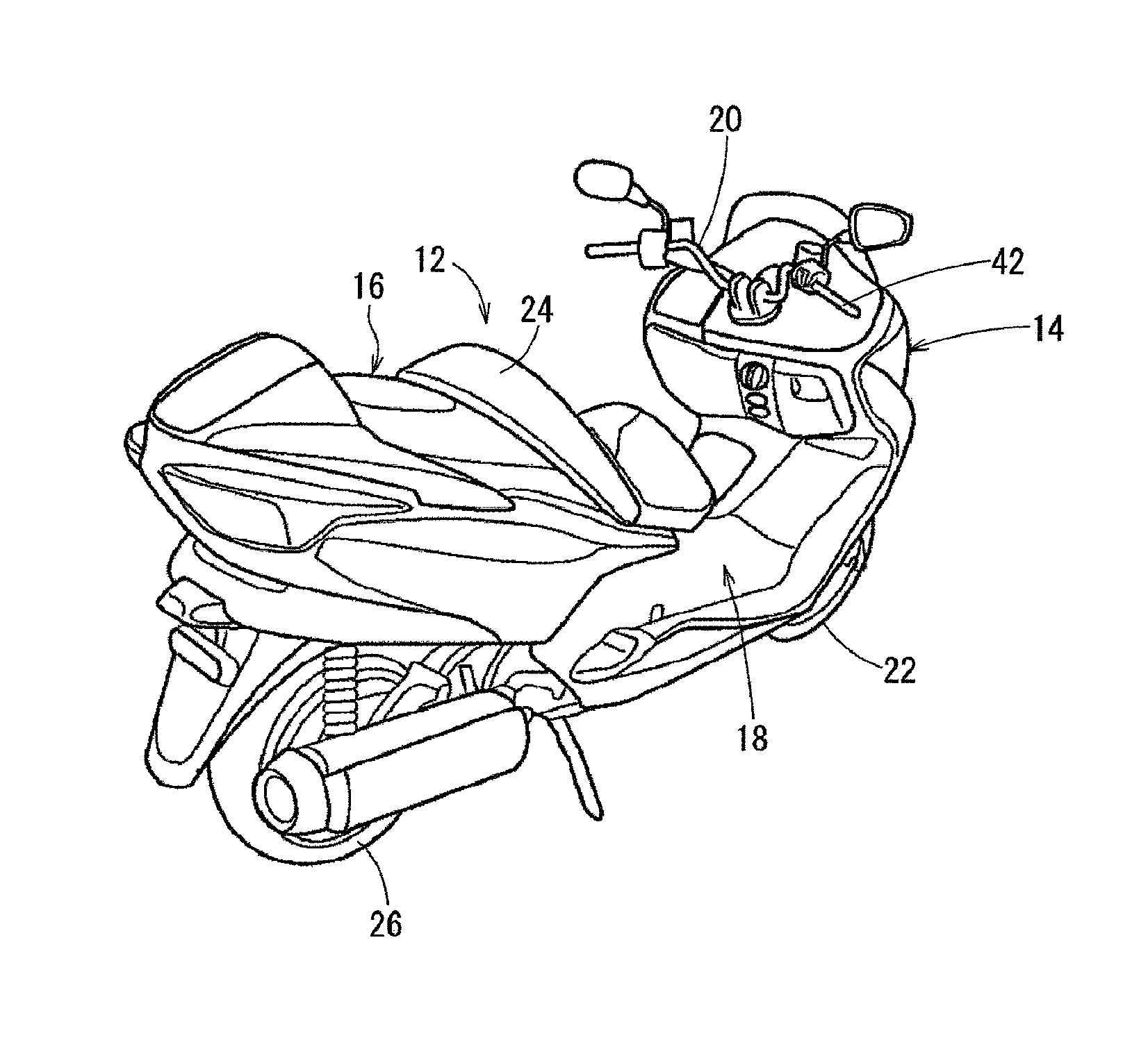
[0047]The motorcycle 12 is constituted such that, as illustrated in FIG. 1, a vehicle-body front part 14 and a vehicle-body rear part 16 are coupled together via a floor part 18 in a low position. The vehicle-body front part 14 includes an upper part on which a handlebar 20 is turnably mounted and a lower part to which a front wheel 22 is journaled. The vehicle-body rear part 16 includes an upper part on which a seat 24 is mounted and a lower part to which a rear wheel 26 is journaled.

[0048]The motorcycle 12 includes an engine 28 where, as schematically illustra...


PUM

PropertyMeasurementUnit
volumeaaaaaaaaaa
timeaaaaaaaaaa
reductionaaaaaaaaaa

Abstract

An exhaust emission purification control device for an engine that accurately estimates an accumulated oxygen amount of a catalyst at a terminating time of a reduction treatment using a simple method. An exhaust emission purification control device for an engine includes a secondary air injector that injects secondary air within an exhaust path. An O2 sensor detects an air-fuel ratio in a downstream side of a catalyst. A count-value accumulator estimates an accumulated oxygen amount (a count value) in the catalyst during the secondary air injection. A rich spike controller performs rich injection after the secondary air injection. This device includes a count-value corrector that multiplies the count value after the secondary air injection by a correction coefficient derived from an output value SVO2 of the O2 sensor during termination of reduction treatment, so as to estimate the accumulated oxygen amount during the termination of the reduction treatment.

Description

CROSS-REFERENCE TO RELATED APPLICATIONS[0001]The present application claims priority under 35 USC 119 to Japanese Patent Application No. 2013-075334 filed Mar. 29, 2013 and Japanese Patent Application No. 2013-075331 filed Mar. 29, 2013 the entire contents of which are hereby incorporated by reference.BACKGROUND OF THE INVENTION[0002]1. Field of the Invention[0003]The present invention relates to an exhaust emission purification control device for an engine. More specifically, to an exhaust emission purification control device for an engine that estimates an accumulated oxygen amount in a catalyst using a counter. In addition, the present invention relates to an exhaust emission purification device for an engine that is preferred to be used in a vehicle (such as a motorcycle) with an internal combustion engine.[0004]2. Description of Background Art[0005]A method for estimating an accumulated oxygen amount in a catalyst using a counter is used in, for example, an exhaust emission pur...

Claims


Application Information

Patent Timeline
Patent Type & Authority Applications(United States)
IPC IPC(8): F01N3/20
CPCF01N3/206F01N3/22F01N11/007F01N2550/03F01N2550/14F01N2570/16F01N2900/0421F02D41/0295F02D41/1454F02D41/2403F02D2200/0814Y02T10/40Y10T29/49345
Inventor TAKANO, YUKIFUJITA, SHINJINAKANO, SHINYASAKIYAMA, SATOKO
Owner HONDA MOTOR CO LTD
Why Eureka
Try Eureka