Transcutaneous electrical nerve stimulator with user gesture detector and electrode-skin contact detector, with transient motion detector for increasing the accuracy of the same

a technology of electrical nerve stimulation and detector, which is applied in the field of transcutaneous electrical nerve stimulation devices with user gesture detectors and electrodeskin contact detectors, and transient motion detectors, can solve the problems of painful tens stimulation, prone to detachment, and cumbersome tens design, and achieve the effect of eliminating false detections of user gestures and eliminating false detections of electrode peeling

Active Publication Date: 2014-10-02
NEUROMETRIX INC
View PDF1 Cites 99 Cited by
  • Summary
  • Abstract
  • Description
  • Claims
  • Application Information

AI Technical Summary

Benefits of technology

[0017]The present invention comprises the provision and use of a novel TENS device which comprises an electrical stimulator and electrodes designed to be placed on a user's upper calf (or other anatomical location) to provide therapeutic electrical stimulation to the user. The novel TENS device allows a tight mechanical coupling and electrical connection between the stimulator and electrodes without the need for lead wires. A user may interact with the novel TENS device through gestures such as tapping the enclosure of the device (as well as through conventional input means such as push buttons). To this end, the novel TENS device provides automated means for eliminating “false” detections of user gestures. In accordance with the present invention, the novel TENS device also monitors the integrity of the electrode-skin interface via impedance measurements and includes automated means for eliminating “false” detections of electrode peeling.
[0018]More particularly, an accelerometer incorporated in the novel TENS device allows the device to continuously monitor user gestures. In addition, the accelerometer also allows the TENS device to monitor user body movement. A key feature of the present invention is that the TENS device uses body movement information, computed from the accelerometer data, in order to improve the accuracy of user gesture recognition and to improve the accuracy of electrode-skin contact monitoring. In particular, specific body movement patterns, as measured by the accelerometer, are used to discriminate between “true” acceleration pulse events representative of intended user gestures and “false” acceleration pulse events representative of unintended user gestures in order to improve the accuracy of user gesture recognition. Specific body movement patterns, as measured by the accelerometer, are also used to discriminate between “true” electrode-skin contact degradation (representative of actual electrode peeling) and “false” electrode-skin contact degradation (representative of transient changes of electrode-skin impedance) in order to improve the accuracy of electrode-skin contact monitoring.
[0019]Inasmuch as the novel TENS device is intended to be worn for extended periods of time, another feature of the present invention is the provision of these capabilities with minimal computational demand and power consumption.
[0021]And in a preferred embodiment of the invention, the TENS device also monitors electrode-skin contact (by measuring impedance across the electrode-skin interface) in real-time, and is configured to stop electrical stimulation if the impedance levels indicate that electrode peeling has occurred (“electrode-skin contact detection”). In a preferred embodiment of the invention, electrode-skin contact detection is integrated with the aforementioned transient motion detection in order to discriminate between “true” electrode-skin contact degradation (representative of actual electrode peeling) and “false” electrode-skin contact degradation (representative of transient changes of electrode-skin impedance caused by ordinary body movements) in order to improve the accuracy of electrode-skin contact monitoring.

Problems solved by technology

In this situation, conventional TENS designs (with their long lead wires) can be too cumbersome and prone to accidental detachment of the lead wires from the handheld unit or from the electrodes, or to accidental detachment of the electrodes from the skin of the user.
For example, in users with painful diabetic neuropathy, pain is felt primarily in the feet and lower legs, and long lead wires (e.g., extending from the waist to electrodes applied to the upper calf of the user) are especially prone to detachment when users are engaged in normal daily activities such as walking or climbing stairs.
Increased current density and power density can lead to painful TENS stimulation and, in the extreme, thermal burns.
While the electrode-skin contact area cannot be easily measured in real-time, the contact area directly affects the impedance to the stimulation current flow, i.e., a reduced electrode-skin contact area will lead to higher impedance.
Furthermore, electric circuit theory imposes a physical limit to the maximum current a stimulator can deliver to the user, based on the maximum voltage range of the stimulator:
However, activities like walking, running, and stair climbing may impose challenges to the accurate detection of intended user gestures and to maintaining a consistent electrode-skin interface.
More particularly, mechanical shocks associated with walking or bumping into objects may be detected and incorrectly interpreted as user-initiated control gestures.
In addition, ordinary body movements can cause momentary changes in the integrity of the electrode-skin contact and may be incorrectly interpreted as problematic and permanent changes in electrode-skin contact, even though such momentary changes in the integrity of the electrode-skin contact pose no real risk to the patient.
Such “false” detections of user gestures, and / or such “false” detection of electrode peeling, can unnecessarily diminish the value of a user gesture detector and / or an electrode peeling detector for a TENS device.

Method used


Image

  • Transcutaneous electrical nerve stimulator with user gesture detector and electrode-skin contact detector, with transient motion detector for increasing the accuracy of the same
  • Transcutaneous electrical nerve stimulator with user gesture detector and electrode-skin contact detector, with transient motion detector for increasing the accuracy of the same
  • Transcutaneous electrical nerve stimulator with user gesture detector and electrode-skin contact detector, with transient motion detector for increasing the accuracy of the same

Examples


Embodiment Construction

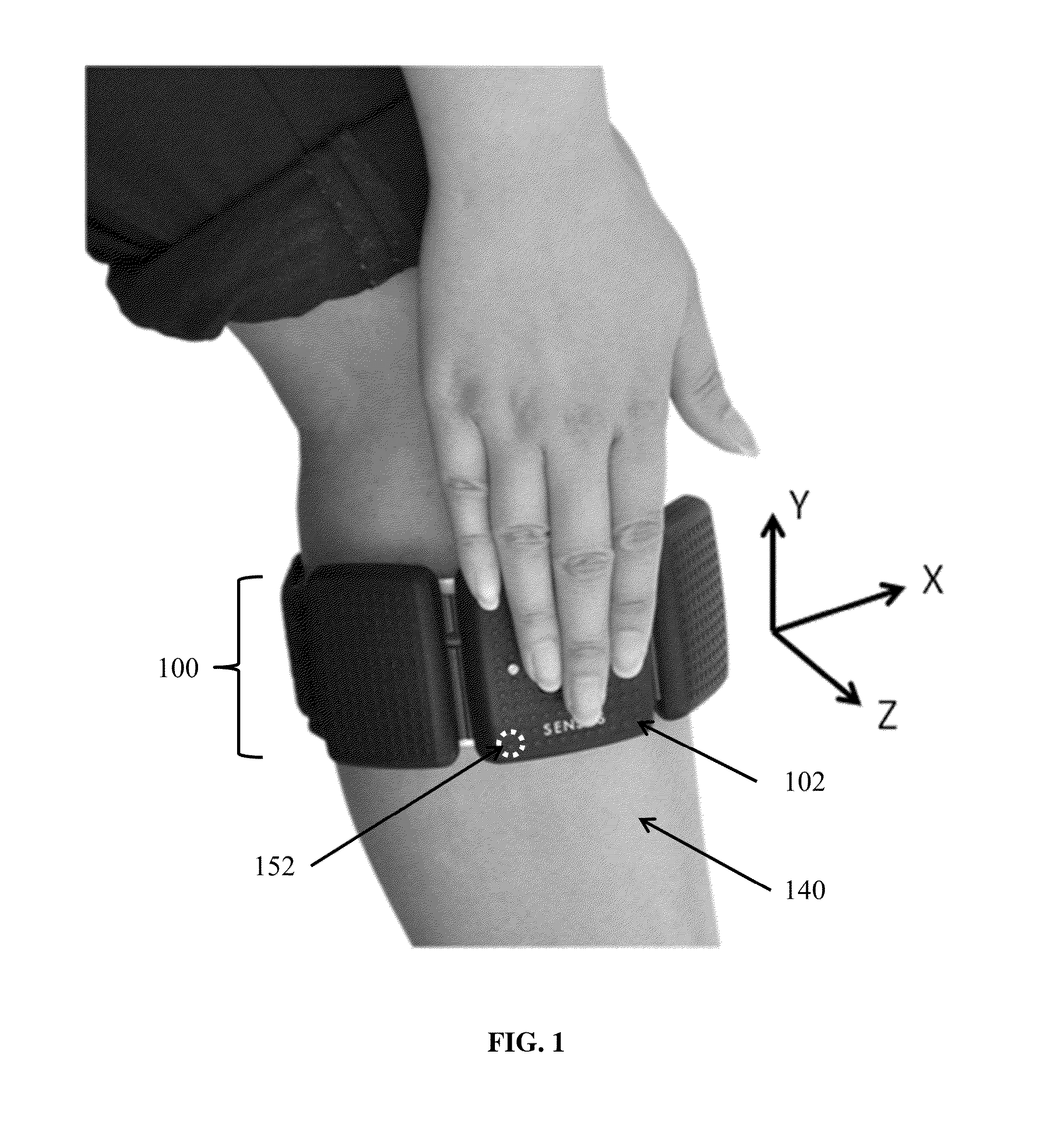
[0070]FIG. 1 illustrates a novel TENS device 100 formed in accordance with the present invention, with the novel TENS device being shown worn on a user's upper calf 140. A user may wear one TENS device 100 on either leg, or wear two TENS devices, one on each leg.

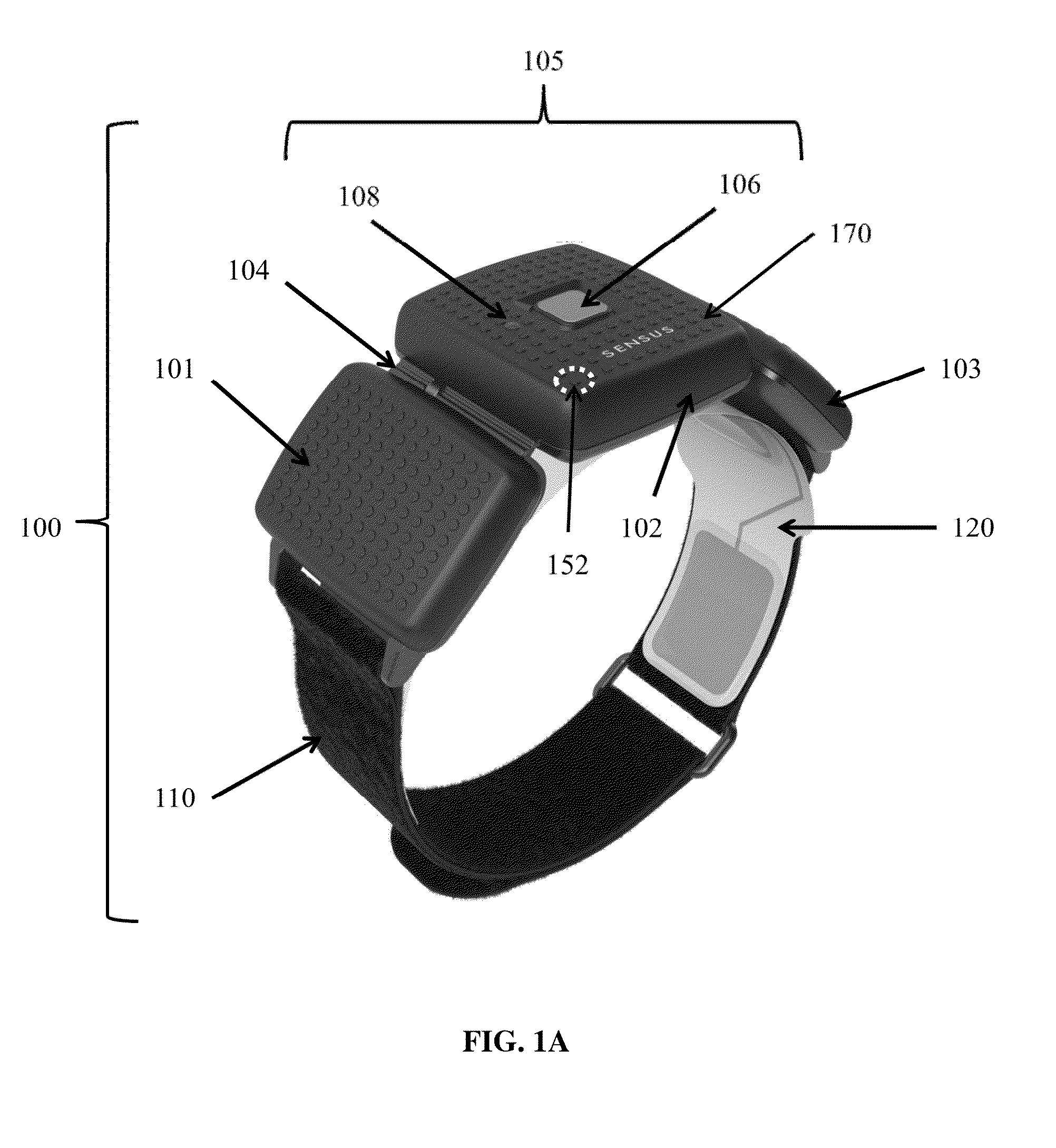
[0071]TENS device 100 is shown in greater detail in FIG. 1A and preferably comprises three components: a stimulator 105, a strap 110, and an electrode array 120 (comprising a cathode electrode and an anode electrode appropriately connected to stimulator 105, as will hereinafter be discussed). Stimulator 105 preferably comprises three mechanically and electrically inter-connected compartments 101, 102, and 103. Compartments 101, 102, 103 are preferably inter-connected by hinge mechanisms 104 (only one of which is shown in FIG. 1A), thereby allowing TENS device 100 to conform to the curved anatomy of a user's leg. In a preferred embodiment, compartment 102 houses the TENS stimulation hardware (except for a battery) and user in...


PUM


Abstract

Apparatus for transcutaneous electrical nerve stimulation in a user, the apparatus comprising:a housing;stimulation means carried by the housing for electrically stimulating at least one nerve;a pair of electrodes releasably mounted to the housing and connectable to the stimulation means for electrical stimulation of the at least one nerve;monitoring means for monitoring user gesture, electrode-skin contact integrity and transient motion;analysis means for analyzing the output of the monitoring means for determining user gesture, electrode-skin contact integrity and transient motion; andcontrol means for controlling the output of the stimulation means in response to the determined user gesture, electrode-skin contact integrity and transient motion.

Description

REFERENCE TO PENDING PRIOR PATENT APPLICATIONS[0001]This patent application:[0002](i) is a continuation-in-part of pending prior U.S. patent application Ser. No. 14 / 230,648, filed Mar. 31, 2014 by Neurometrix, Inc. and Shai Gozani et al. for DETECTING CUTANEOUS ELECTRODE PEELING USING ELECTRODE-SKIN IMPEDANCE (Attorney's Docket No. NEURO-64), which claims benefit of prior U.S. Provisional Patent Application Ser. No. 61 / 806,481, filed Mar. 29, 2013 by Shai Gozani for DETECTING ELECTRODE PEELING BY RELATIVE CHANGES IN SKIN-ELECTRODE IMPEDANCE (Attorney's Docket No. NEURO-64 PROV);[0003](ii) is a continuation-in-part of pending prior U.S. patent application Ser. No. 14 / 253,628, filed Apr. 15, 2014 by Neurometrix, Inc. and Shai Gozani et al. for TRANSCUTANEOUS ELECTRICAL NERVE STIMULATOR WITH AUTOMATIC DETECTION OF USER SLEEP-WAKE STATE (Attorney's Docket No. NEURO-65), which claims benefit of prior U.S. Provisional Patent Application Ser. No. 61 / 811,864, filed Apr. 15, 2013 by Shai Goz...

Claims


Application Information

Patent Timeline
Patent Type & Authority Applications(United States)
IPC IPC(8): A61N1/36
CPCA61N1/36021A61B2562/0219A61N1/0492A61B2560/0276G06F3/015G06F3/017A61N1/08A61B5/11A61N1/0456A61N2001/083G06F3/0346A61N1/3603
Inventor FERREE, THOMASKONG, XUANAGUIRRE, ANDRESWILLIAMS, MICHAELGOZANI, SHAI N.
Owner NEUROMETRIX INC
Why Eureka
Try Eureka