Centrifugal Separator and Filter Arrangement Having a Centrifugal Separator of Said Type
- Summary
- Abstract
- Description
- Claims
- Application Information
AI Technical Summary
Benefits of technology
Problems solved by technology
Method used
Image

Examples
Embodiment Construction
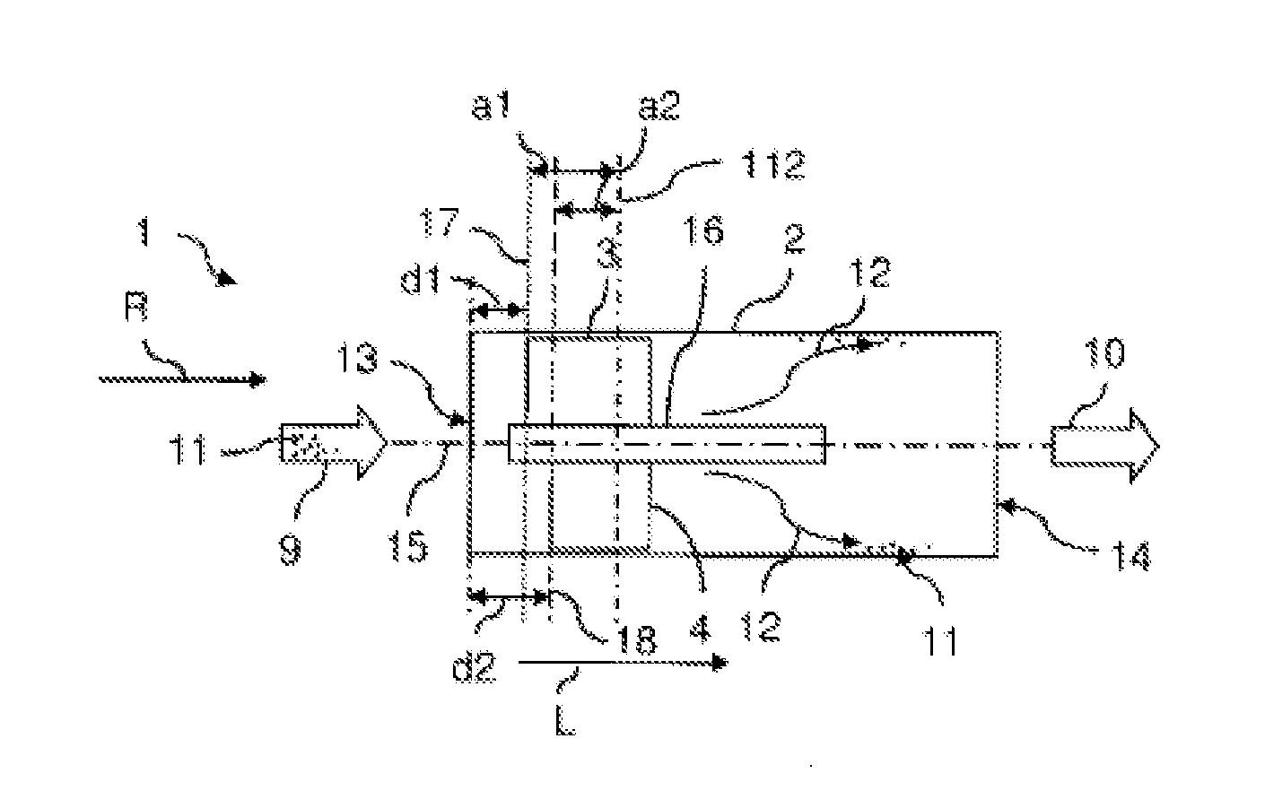
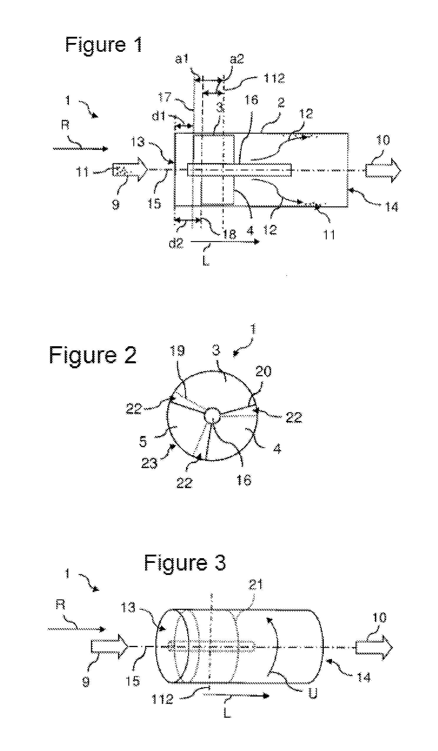
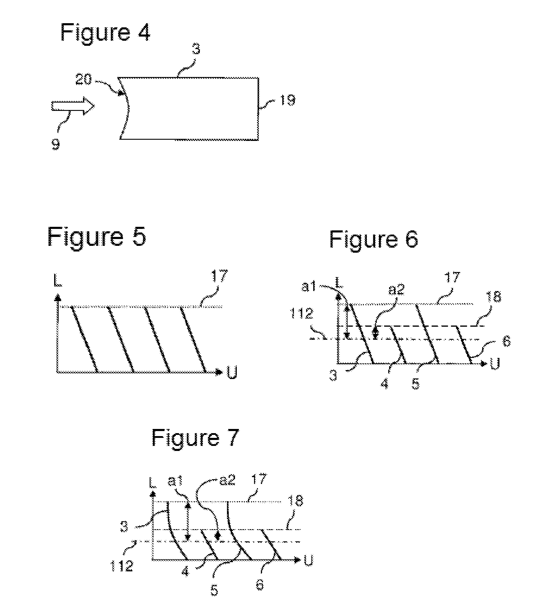
[0061]FIG. 1 shows a schematic longitudinal section view of an embodiment of a centrifugal separator. FIGS. 2 and 3 show cross-section views and perspective views of the embodiment.
[0062]In a centrifugal or cyclone separator, particles are removed from a fluid laden with particles. This is indicated in FIG. 1 by an arrow representing a raw fluid flow 9. The raw fluid 9, for example air for an internal combustion engine, can contain dust or other particles 11. After passing through a suitable centrifugal separator 1, that is configured, for example, as an axial cyclone, purified air or fluid 10 flows out.
[0063]The centrifugal separator 1 has a substantially cylindrical housing 2. The housing 2 or the centrifugal separator 1 has a longitudinal axis 15 which, in the embodiment of the FIGS. 1 to 3, corresponds also to a symmetry axis. On the inflow side, an inflow opening 13 is provided, and an outflow opening 14 is provided on the outflow side. In the centrifugal separator 1, a swirl i...
PUM
| Property | Measurement | Unit |
|---|---|---|
| Length | aaaaa | aaaaa |
| Thickness | aaaaa | aaaaa |
| Angle | aaaaa | aaaaa |
Abstract
Description
Claims
Application Information
 - Generate Ideas
- Intellectual Property
- Life Sciences
- Materials
- Tech Scout
- Unparalleled Data Quality
- Higher Quality Content
- 60% Fewer Hallucinations
Browse by: Latest US Patents, China's latest patents, Technical Efficacy Thesaurus, Application Domain, Technology Topic, Popular Technical Reports.
© 2025 PatSnap. All rights reserved.Legal|Privacy policy|Modern Slavery Act Transparency Statement|Sitemap|About US| Contact US: help@patsnap.com