
Method of Calibrating an Inertial Assembly Comprising a Dynamic Phase Between Two Static Phases

a dynamic phase and inertial assembly technology, applied in the direction of speed/acceleration/shock measurement, speed/acceleration/shock measurement, test/calibration of speed/acceleration/shock measurement devices, etc., can solve the problem of inability to achieve extremely simple calibration techniques, and achieve good performance

Active Publication Date: 2014-10-09
SAFRAN ELECTRONICS & DEFENSE
View PDF18 Cites 7 Cited by
  • Summary
  • Abstract
  • Description
  • Claims
  • Application Information

AI Technical Summary

Benefits of technology

The invention proposes calibration means that are easy to use and perform well. This means that calibration can be done quickly without needing an external reference for position or force.

Problems solved by technology

That extremely simple calibration technique is nevertheless not possible when the inertial unit is mounted on a support that does not allow for the various orientations needed for performing the calibration.
The set of processing parameters is selected to minimize at least some of the errors of the inertial unit for calibration, however it is affected by errors of the reference inertial unit and by errors in positioning the reference inertial unit relative to the inertial unit for calibration.

Method used


Image

  • Method of Calibrating an Inertial Assembly Comprising a Dynamic Phase Between Two Static Phases
  • Method of Calibrating an Inertial Assembly Comprising a Dynamic Phase Between Two Static Phases

Examples


Embodiment Construction

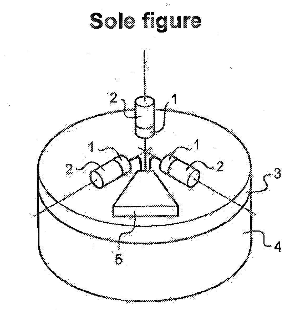
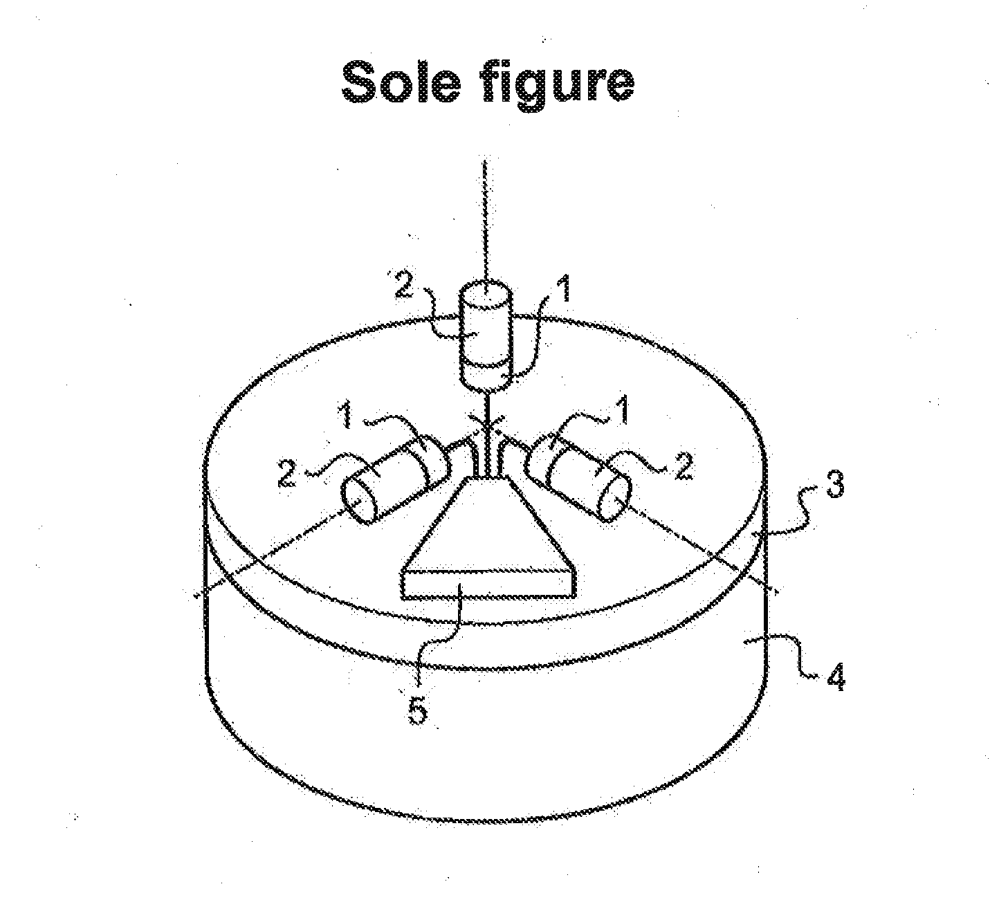
[0022]In known manner, the inertial unit comprises three accelerometers 1 and three angle sensors 2 of the gyro type, mounted on a frame 3 carried by a steerable support 4, specifically a tripod, enabling the frame to be pivoted about a first axis that is substantially in alignment with the vertical (azimuth pivoting) and includes orientation means enabling the first axis to be moved angularly to a limited extent about the vertical. The accelerometers and the angle sensors have axes substantially in alignment on the axes X, Y, Z of a measurement frame of reference and they are connected to a control unit 5.

[0023]The control unit 5 has calculation means, such as a microprocessor, and a memory containing a control and processing program to be executed by the calculation means.

[0024]The control and processing program is arranged in known manner to acquire measurement signals from the accelerometers 1 and the angle sensors 2, and to perform at least some processing thereon.

[0025]The con...


PUM


Abstract

A method of calibrating an inertial unit is provided. During a first static stage, in which the inertial unit is in a first orientation, measurements are taken by means of the accelerometers and the inertial rotation sensors. During a dynamic stage, the orientation of the inertial unit is changed, at least in part in azimuth, from the first orientation towards a second orientation, while taking measurements by means of the inertial rotation sensors. During a second static stage, in which the inertial unit is in the second position, measurements are taken by means of the accelerometers and of the inertial rotation sensors. For each static stage, a direction, an amplitude, and a mean speed of rotation for apparent gravity in an inertial frame of reference is estimated, variation is calculated in orientation between the static stages, and the accelerometer biases is deduced therefrom.

Description

BACKGROUND OF THE INVENTION[0001]1. Field of the Invention[0002]The present invention relates to a method of calibrating an inertial unit having accelerometers and angle sensors.[0003]2. Brief Discussion of the Related Art[0004]In general, an inertial unit has three accelerometers and three angle sensors of the gyro type mounted on a frame. The accelerometers and the angle sensors have axes that are substantially in alignment with the axes of a measurement frame of reference and they are connected to a control unit that serves to acquire measurement signals from the accelerometers and the angle sensors and to process them, at least in part.[0005]Accelerometers and sensors present defects, such as biases and drifts, and it is necessary to know them in order to take them into account when processing the measurement signals so as to improve the accuracy of the inertial unit.[0006]For this purpose, it is common practice to calibrate the inertial unit before using it.[0007]Calibration se...

Claims


Application Information

Patent Timeline
IPC IPC(8): G01C25/00G01P21/00
CPCG01C25/005G01P21/00G01C25/00
Inventor BECHERET, YVES
Owner SAFRAN ELECTRONICS & DEFENSE
Learn More