Lighting Device for Respiratory Humidifier and Respiratory Humidifier

a technology of light source and humidifier, which is applied in the direction of instruments, lighting and heating apparatus, audible signalling systems, etc., can solve the problems of limited capacity to provide a clear, optically recognizable signal, etc., and achieves the effect of reducing the number of lamps

Active Publication Date: 2014-10-09
HAMILTON MEDICAL AG
View PDF8 Cites 1 Cited by
  • Summary
  • Abstract
  • Description
  • Claims
  • Application Information

AI Technical Summary

Benefits of technology

[0015]At the same time, it is advantageous for the internal surface of the light entrance portion to have at least a matte or structured finish. What this achieves is that the light beam, even if it is quite small, is scattered as widely as possible within the liquid container.
[0016]It is also advantageous for the light source or light-producing means to comprise one or more light-emitting diodes (LEDs). Alternatively, however, it is also possible to use other types of light sources such as halogen lamps, incandescent lamps, lasers, or other suitable means of illumination. In particular, it is advantageous for the light source to be multicolored; this can be achieved, for example, by the use of a multicolored LED array. This offers the possibility of creating an alarm code, according to which different functional alarms are identified by separate colors.
[0017]It is also advantageous for the inside surface of the bottom plate to be polished, which then reflects the incident light more effectively. This leads in turn to a higher light yield during the time that the container is being illuminated.
[0018]Also according to the invention is a respiratory humidifier with a housing, a liquid container, and a lighting device as defined above. The respiratory humidifier preferably comprises a control unit, which is

Problems solved by technology

Because of the small dimensions of the control unit, there is only a limited capacity to provide a cle

Method used


Image

  • Lighting Device for Respiratory Humidifier and Respiratory Humidifier
  • Lighting Device for Respiratory Humidifier and Respiratory Humidifier
  • Lighting Device for Respiratory Humidifier and Respiratory Humidifier

Examples


Embodiment Construction

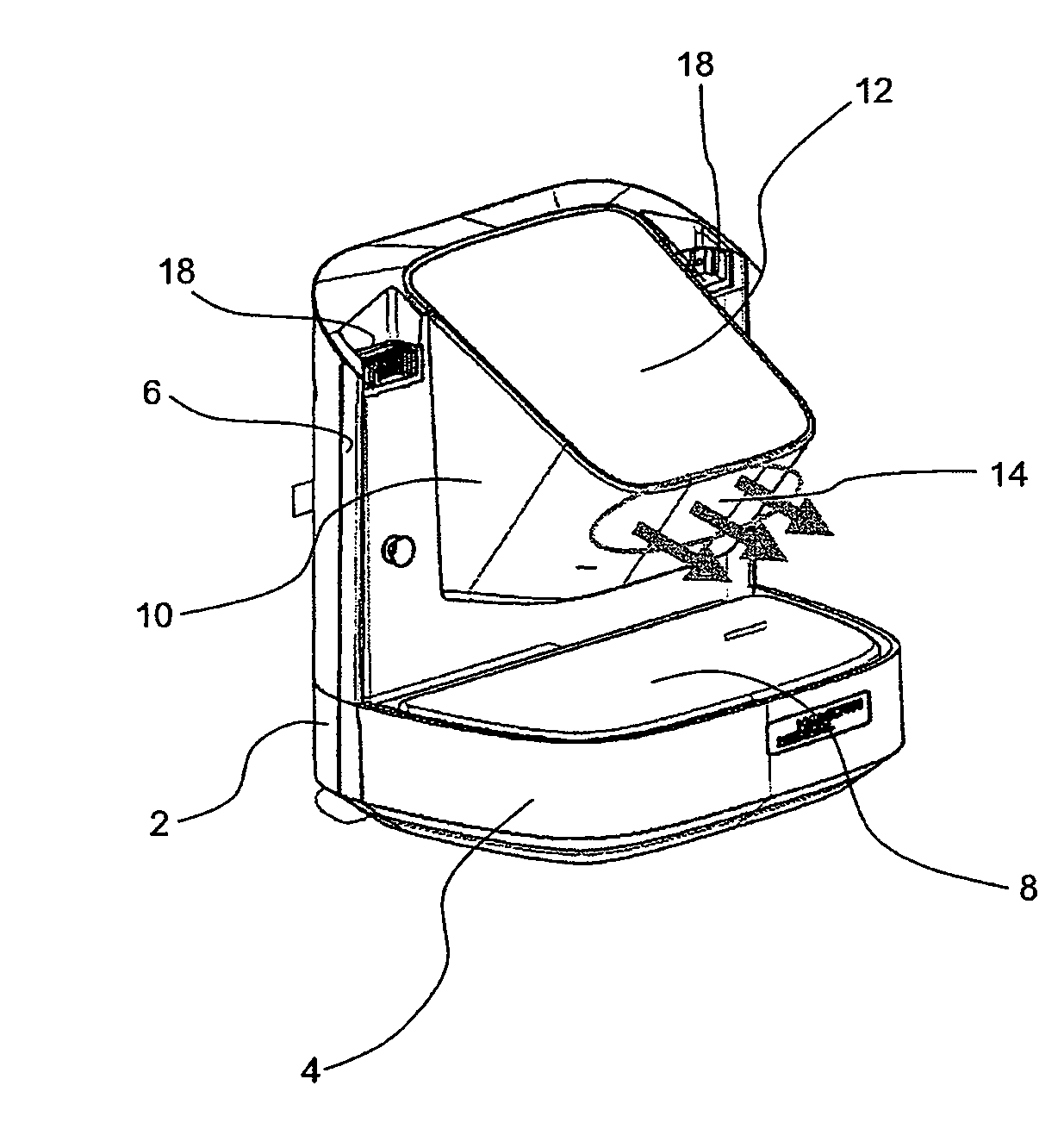
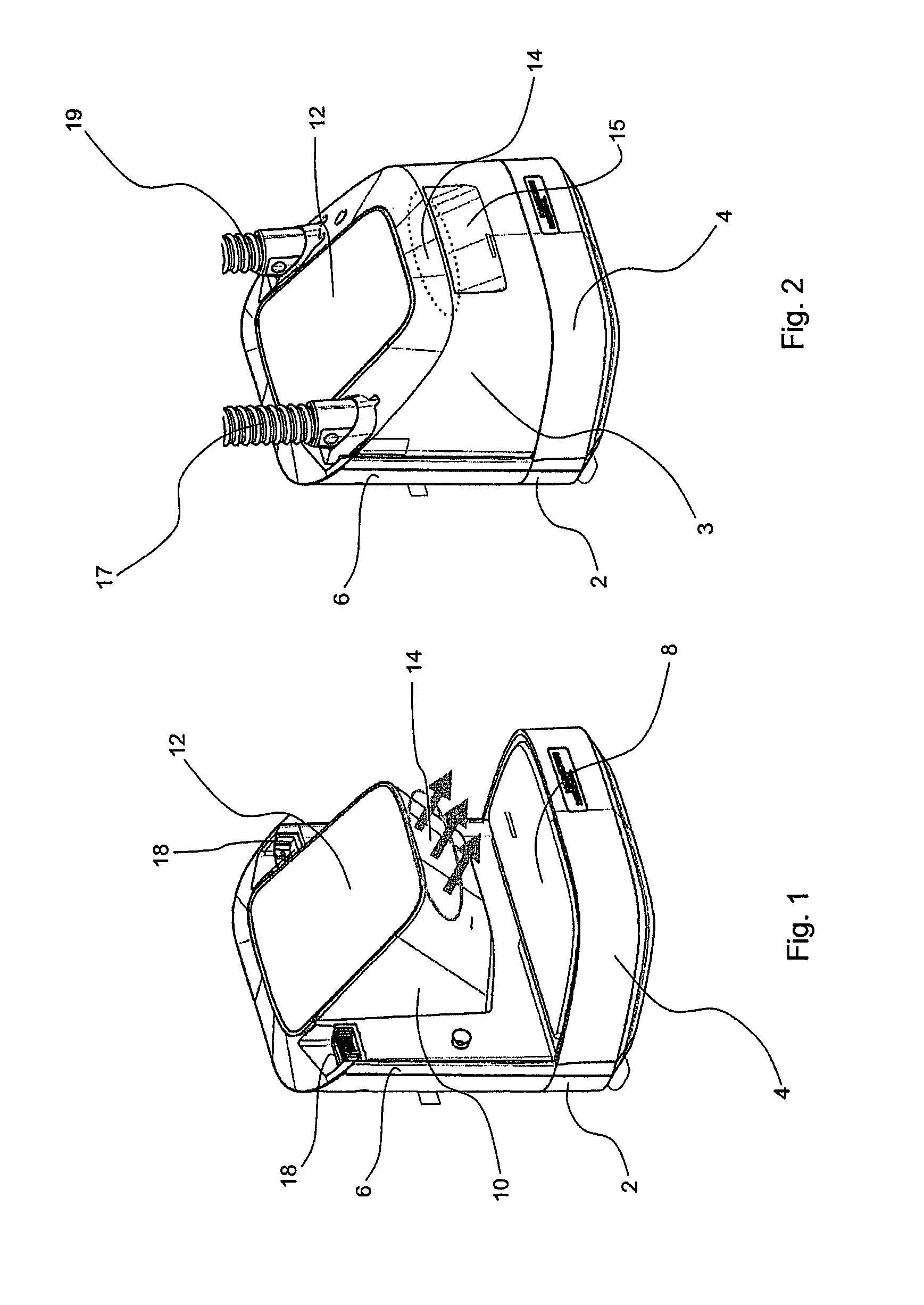
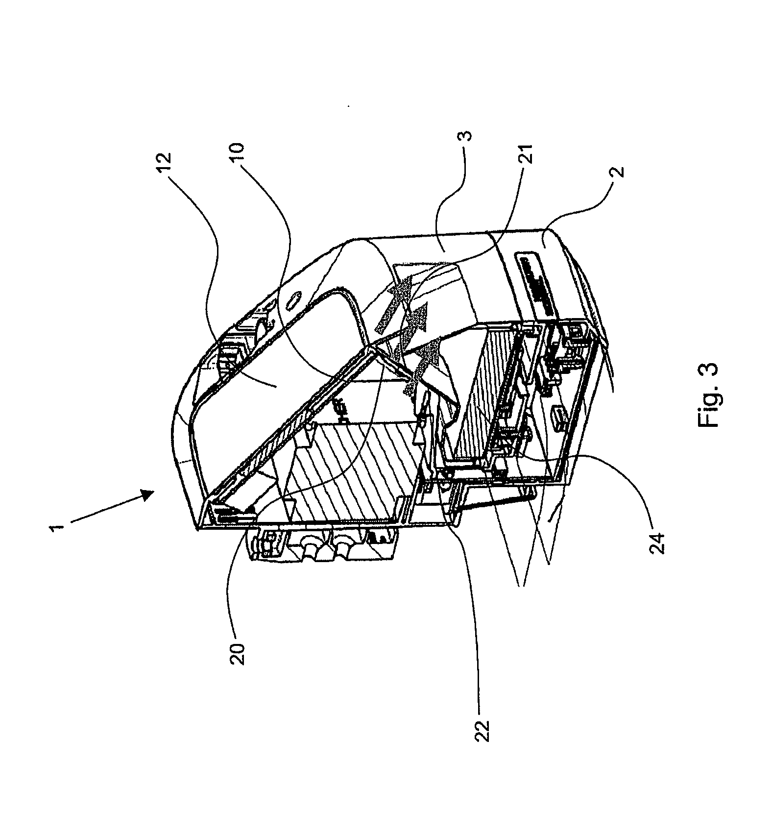
[0027]FIG. 1 shows a perspective view of the housing 2 of a respiratory humidifier which comprises a lighting device according to a preferred embodiment of the present invention. The housing 2 comprises essentially an L-shape with a horizontal part 4 and a vertical part 6. On the horizontal part 4, a heating plate 8 is arranged, which is oriented essentially horizontally and which covers almost the entire upward-facing surface of the horizontal part 4. A projecting portion 10 extends from approximately the middle of the upper, free end of the vertical part 6, the slanted surface of which portion comprises a user interface 12. The user interface 12 comprises a display devices and operating elements 16 (not shown), by means of which, together with a control unit (not shown), the respiratory humidifier can be monitored and controlled. Electrical contact elements 18 are arranged at the upper end of the vertical part 6, offset laterally from the projecting portion 10; these elements can ...


PUM


Abstract

A lighting device for a respiratory humidifier (1) is provided, the humidifier comprising a liquid container (3) with a bottom plate and a housing (2) with a heating plate (8), wherein the heating plate (8) can be heated for heating the liquid in the liquid container (3), and wherein the bottom plate can be brought into contact with the heating plate (8), wherein the housing (2) comprises a light source (20) and a light exit portion (22), and the liquid container (3) comprises a light entrance portion (21), wherein the light proceeding from the light source (20) proceeds in a lighting direction through the light exit portion (22) and the light entrance portion (21) and thus arrives in the liquid container (3).

Description

FIELD OF THE INVENTION[0001]The present invention pertains to a lighting device for a respiratory humidifier for ventilating patients with breathing gas.BACKGROUND OF THE INVENTION[0002]When patients are being mechanically ventilated on an intensive-care ward, for example, the patient to be ventilated is connected pneumatically to the ventilator or respiratory apparatus by a system of ventilation tubing. Because the breathing gas delivered to the patient must be adjusted with respect to temperature and humidity to meet the physiological needs of the patient, a respiratory humidifier is arranged in the inhalation or inspiration tube to heat and humidify the breathing gas. The respiratory humidifier comprises a liquid container filled with distilled water, through which the inhalation or inspiration gas is conducted and humidified.[0003]The heating of the liquid in the liquid container is usually accomplished by means of a heating plate in the bottom part of the housing of the respira...

Claims


Application Information

Patent Timeline
IPC IPC(8): A61M16/00F21V33/00
CPCF21V33/0068A61M16/0051A61M16/1075A61M16/16A61M2205/18A61M2205/3368A61M2205/3389A61M2205/502A61M2205/581A61M2205/583A61M2205/587A61M16/109A61M16/021
Inventor BUECHI, RUDOLF
Owner HAMILTON MEDICAL AG
Why Eureka
Try Eureka