Die tool, device and method for producing a lens wafer

Active Publication Date: 2017-08-22
EV GRP
View PDF51 Cites 1 Cited by
  • Summary
  • Abstract
  • Description
  • Claims
  • Application Information

AI Technical Summary

Benefits of technology

The invention is a tool and method for producing lens wafers with microlenses in mass production. The tool is designed to automatically create the lens field, simplifying the processing of the lens field. The tool also allows for the production of different types of lens shapes and can detect orientation marks for orientation and wedge error compensation. The device includes a lift drive for precise movement of the holding system in the Z-direction and can cause the second die to tip over. The technical effects of the invention are improved production accuracy and efficiency for lens wafer production.

Problems solved by technology

The more the microlenses are to be miniaturized, the more difficult will be their optically correct production, since at the same time, there is an enormous cost pressure for the microlenses that are ideally to be produced in mass production.
In the production of unsupported microlens fields, the shrinkage of the lens field material is problematic during the production of the lens field, in particular during embossing and curing.

Method used


Image

  • Die tool, device and method for producing a lens wafer
  • Die tool, device and method for producing a lens wafer
  • Die tool, device and method for producing a lens wafer

Examples


Embodiment Construction

[0044]In the figures, advantages and features of the invention are characterized with these identifying reference numbers in each case according to the embodiments of the invention, whereby components or features with the functions that are the same or that act the same are characterized with identical reference numbers.

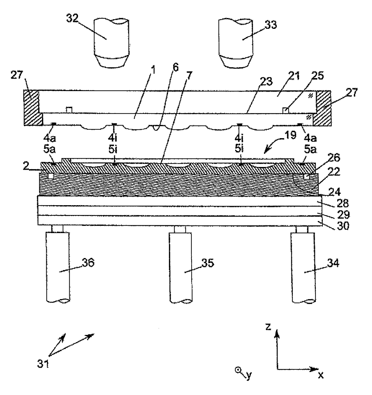
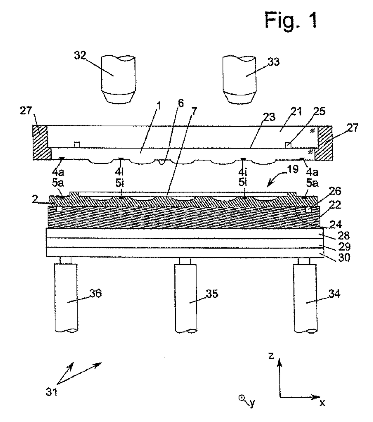
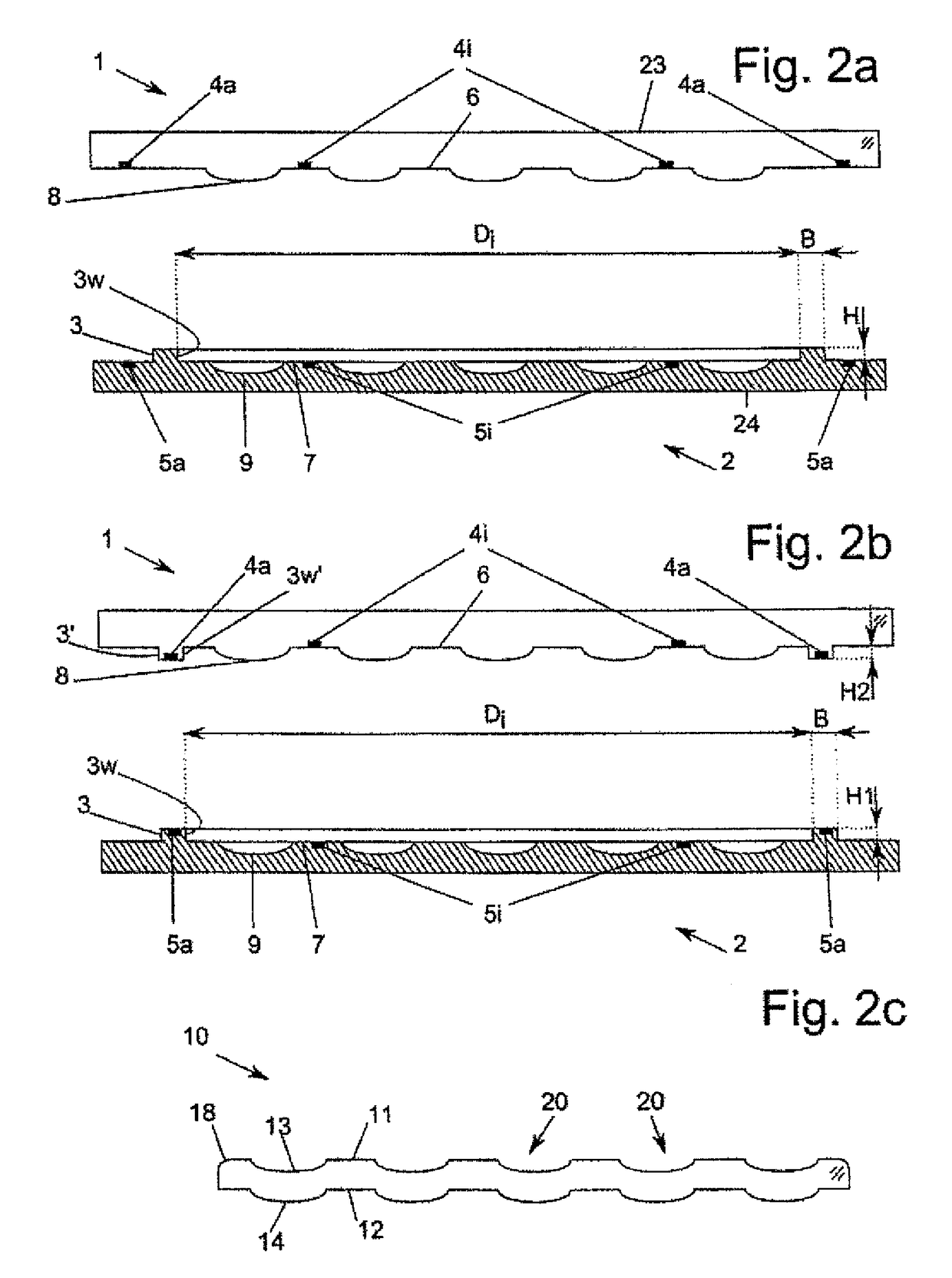
[0045]In FIG. 1, a system that consists of a device according to the invention with a die tool according to the invention is shown. The die tool consists of a first die 1 and a second die 2, and the die tool is shown in detail in a first and second embodiment according to FIGS. 2a and 2b and further described below. In FIG. 1, the die tool is used in the device according to the embodiment shown in FIG. 2a.

[0046]The first die 1 is fixed on its first holding side 23, in particular horizontally, by at least one vacuum strip 25 on a first holding system 21. The first holding system 21 is fixed rigidly and as vibration-free as possible by a particularly annular, preferab...


PUM

PropertyMeasurementUnit
Forceaaaaaaaaaa
Areaaaaaaaaaaa

Abstract

This invention relates to a die tool, a device and a method for producing, in particular embossing, a monolithic lens wafer that has a large number of microlenses.

Description

FIELD OF THE INVENTION[0001]This invention relates to a die tool, a device and a method for producing, in particular embossing, a monolithic lens wafer that has a large number of microlenses.BACKGROUND OF THE INVENTION[0002]Microlenses are primarily used for devices that require an optical focusing system, such as, for example, for cameras of mobile telephones. Because of the push for miniaturization, functional areas are to be smaller and smaller. The more the microlenses are to be miniaturized, the more difficult will be their optically correct production, since at the same time, there is an enormous cost pressure for the microlenses that are ideally to be produced in mass production. In the prior art, microlenses are produced on a carrier substrate by different production methods, as shown in, for example, U.S. Pat. No. 6,846,137 B1, U.S. Pat. No. 5,324,623, U.S. Pat. No. 5,853,960 and U.S. Pat. No. 5,871,888. It is a common aspect of all previously-mentioned methods that, based ...

Claims


Application Information

Patent Timeline
IPC IPC(8): B29D11/00G02B3/00
CPCB29D11/00951B29D11/0048B29D11/00307B29D11/00365G02B3/0031B29D11/005G02B3/0062G02B13/0085
Inventor KAST, MICHAELWIMPLINGER, MARKUS
Owner EV GRP
Why Eureka
Try Eureka