
Composite hat stiffener, composite hat-stiffened pressure webs, and methods of making the same

a technology of pressure web and composite hat, which is applied in the direction of stringers, other domestic articles, transportation and packaging, etc., can solve the problems of high pull-off load of known i-beam stiffened composite panels reinforced with such known i-beam stiffeners, increase production time, increase part count and expense, etc., to improve composite stiffeners and composite stiffen structures.

Active Publication Date: 2014-10-09
THE BOEING CO
View PDF5 Cites 13 Cited by
  • Summary
  • Abstract
  • Description
  • Claims
  • Application Information

AI Technical Summary

Benefits of technology

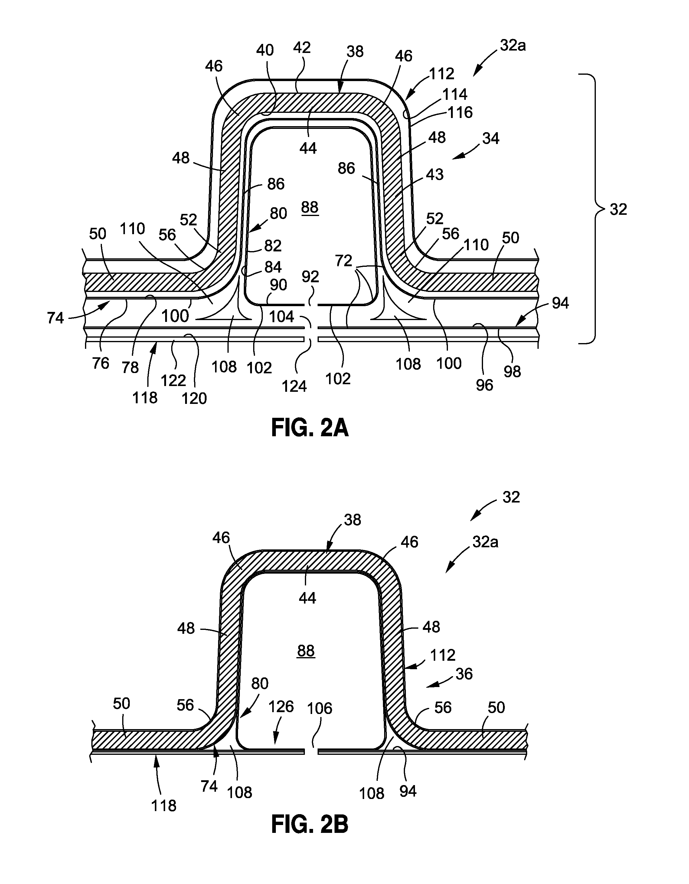
The patent describes a new type of composite stiffener that is used to reinforce structures, such as hats or pressure webs, that are made of materials like carbon fiber. The new stiffener is made by curing a pre-cured composite hat stiffener in a tool, which includes a composite hat section and three layers of stiffening plies. The stiffener is designed to reduce the effects of pull-off load and improve the stability of the structure it is reinforcing. The patent also describes a method for making a composite hat-stiffensed pressure web using the new stiffener. The resulting structure is stronger and more stable, and its design minimizes the risk of failure caused by the pull-off load.

Problems solved by technology

However, known I-beam stiffened composite panels reinforced with such known I-beam stiffeners may experience high pull-off loads at the radius filler, i.e., “noodle”, portions of the I-beam stiffener or at the radius common to the attached flange of the reinforcing stiffener in the region of the noodle.
However, the use of such numerous additional radius filler elements, fasteners, and / or angle fittings may result in increased production time, increased part count and expense, increased labor and manufacturing costs to install and maintain the parts, and an overall increase in the complexity of the structure.
Such specialized tooling may result in further increased labor and manufacturing costs.

Method used


Image

  • Composite hat stiffener, composite hat-stiffened pressure webs, and methods of making the same
  • Composite hat stiffener, composite hat-stiffened pressure webs, and methods of making the same
  • Composite hat stiffener, composite hat-stiffened pressure webs, and methods of making the same

Examples


Embodiment Construction

[0030]Disclosed embodiments will now be described more fully hereinafter with reference to the accompanying drawings, in which some, but not all of the disclosed embodiments are shown. Indeed, several different embodiments may be provided and should not be construed as limited to the embodiments set forth herein. Rather, these embodiments are provided so that this disclosure will be thorough and complete and will fully convey the scope of the disclosure to those skilled in the art.

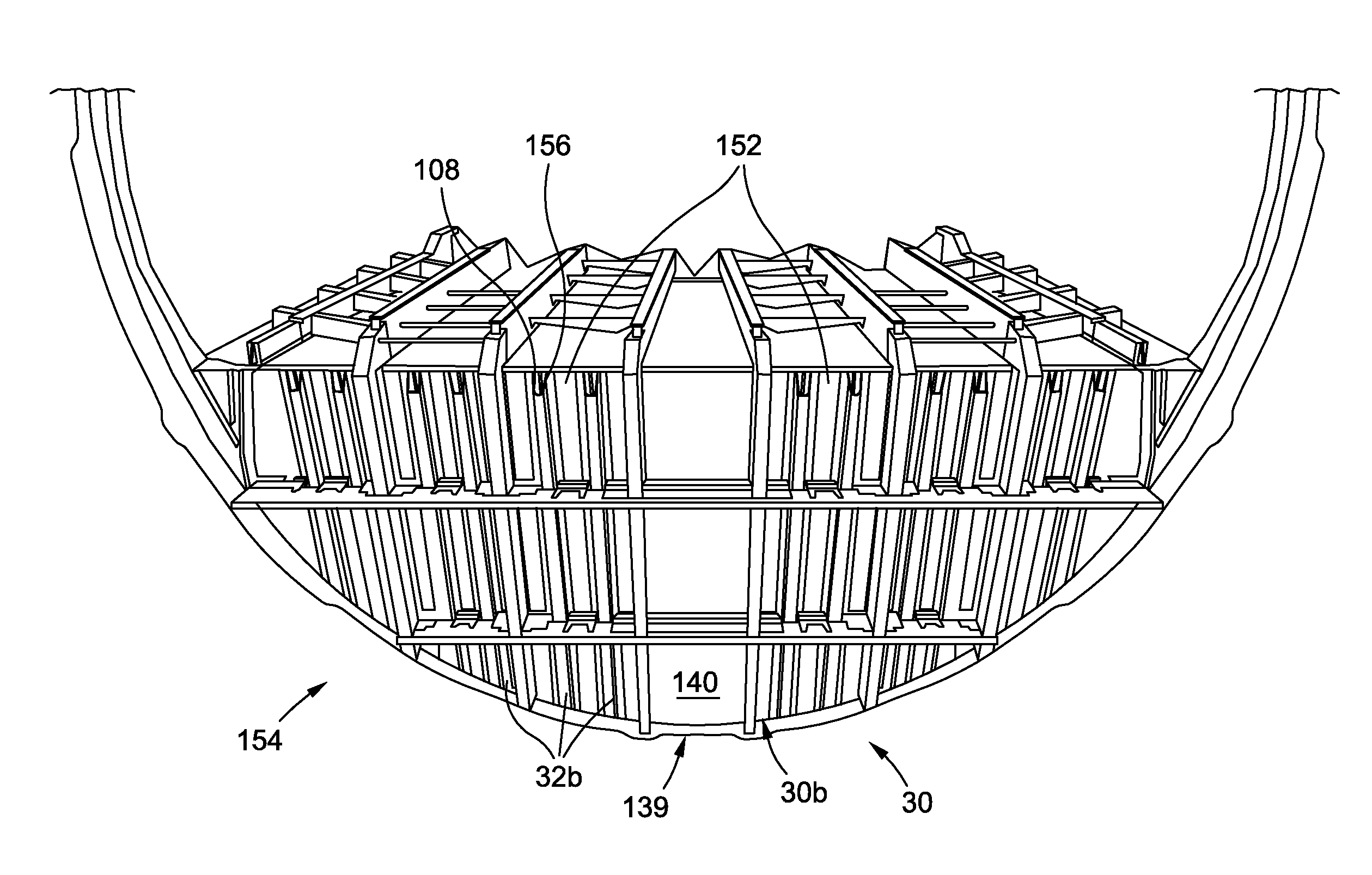
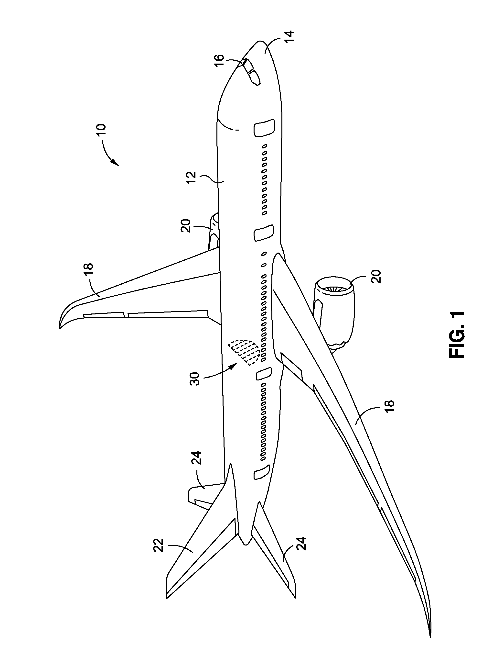
[0031]Now referring to the Figures, FIG. 1 is an illustration of a perspective view of an aircraft 10 that may incorporate one or more exemplary embodiments of a composite hat-stiffened pressure web 30 (see also FIGS. 6A, 7, 8) of the disclosure. As shown in FIG. 1, the aircraft 10 comprises a fuselage 12, a nose 14, a cockpit 16, wings 18, one or more propulsion units 20, a vertical tail portion 22, and horizontal tail portions 24. Although the aircraft 10 shown in FIG. 1 is generally representative of a ...


PUM

PropertyMeasurementUnit
size angleaaaaaaaaaa

Abstract

There is provided a method of making a composite hat stiffener. The method has the steps of curing a composite hat stiffener in a hat tool to form a pre-cured composite hat stiffener. The pre-cured composite hat stiffener has a composite hat section, a plurality of composite stiffening plies with a body ply, a wrap ply, and a base ply, all coupled to the composite hat section, wherein the body ply is coupled to a first side of the composite hat section, the wrap ply is coupled to the body ply, and the base ply is coupled to the body ply and the wrap ply, a pair of radius filler noodles coupled to the composite hat section and disposed between the plurality of composite stiffening plies, and an outer ply coupled to the composite hat section. The method further includes bonding the pre-cured composite hat stiffener to a structure surface.

Description

CROSS-REFERENCE TO RELATED APPLICATIONS[0001]The present application is a continuation of and claims priority to pending application Ser. No. 13 / 531,583, filed Jun. 24, 2012, and entitled COMPOSITE HAT STIFFENER, COMPOSITE HAT-STIFFENED PRESSURE WEBS, AND METHODS OF MAKING THE SAME, the entire contents of which is incorporated herein by reference.BACKGROUND[0002]1) Field of the Disclosure[0003]The disclosure relates generally to composite reinforcing support structures, and more specifically, to composite hat stiffener configurations and methods used in forming composite hat-stiffened pressure webs, such as for use in aircraft.[0004]2) Description of Related Art[0005]Composite structures are used in a wide variety of applications. In aircraft construction, composites are used in increasing quantities to form the fuselage, wings, tail section and other components. For example, aircraft fuselage structures, such as bulkheads and pressure decks, may be formed of composite stiffened pan...

Claims


Application Information

Patent Timeline
Patent Type & Authority Applications(United States)
IPC IPC(8): B29C70/46B29C70/54
CPCB29C70/545B29C70/462B29C70/865B29D99/0003B64C1/064B64C1/10B64C2001/0072B64C1/06Y10T428/24488Y10T156/1028Y10T428/24628B29D99/0005Y02T50/40B64C1/12B29C70/06B32B1/00B64C3/18B64C3/26
Inventor PEARSON, STEVEN E.WHITMER, MATTHEW M.DIXON, REBECCA M.FIRKO, JASON L.MARCINIAK, DOUGLAS G.COMINSKY, KENNETH D.ANDREWS, MARTIN G.
Owner THE BOEING CO
Learn More