Device for the manufacture of a bonded component from fibre-reinforced plastics and also a method

a technology of fiber reinforced plastics and bonded components, which is applied in the direction of dough shaping, manufacturing tools, applications, etc., can solve the problems of unavoidable cure in an autoclave, essentially occurring undesirable voids, and further undesirable voids, etc., and achieve tight tolerances

Inactive Publication Date: 2014-10-09
AIRBUS OPERATIONS GMBH
View PDF1 Cites 3 Cited by
  • Summary
  • Abstract
  • Description
  • Claims
  • Application Information

AI Technical Summary

Benefits of technology

[0010]The object of the invention is therefore to specify a device for the manufacture using moulds of complex, integrally reinforced, bonded components from fiber-reinforced plastic, in which the parasitic cavities only occur to a reduced extent, so that even bonded components with minimum material thicknesses with tight tolerances can be produced without complex rework steps.

Problems solved by technology

As a general rule, curing in an autoclave is unavoidable if the pressure forces that can be achieved by means of a vacuum are insufficient.
However, in addition to the form-defining cavities that are required for the design of the bonded component, further undesirable voids are present.
These undesirable voids essentially ensue as a result of gaps and / or capillaries between molding tools.
As a rule these undesirable cavities fill up during the curing process at least partly with matrix material, since as a result of a pressure difference a transfer of material takes place from the laminates and into the voids.
In particular in zones in which many parasitic cavities are located close to one another, such as, for example in the region of the end faces of a bonded component, there is often a failure to maintain the minimum permissible laminate thickness, which makes cost-intensive rework necessary.

Method used


Image

  • Device for the manufacture of a bonded component from fibre-reinforced plastics and also a method
  • Device for the manufacture of a bonded component from fibre-reinforced plastics and also a method
  • Device for the manufacture of a bonded component from fibre-reinforced plastics and also a method

Examples


Embodiment Construction

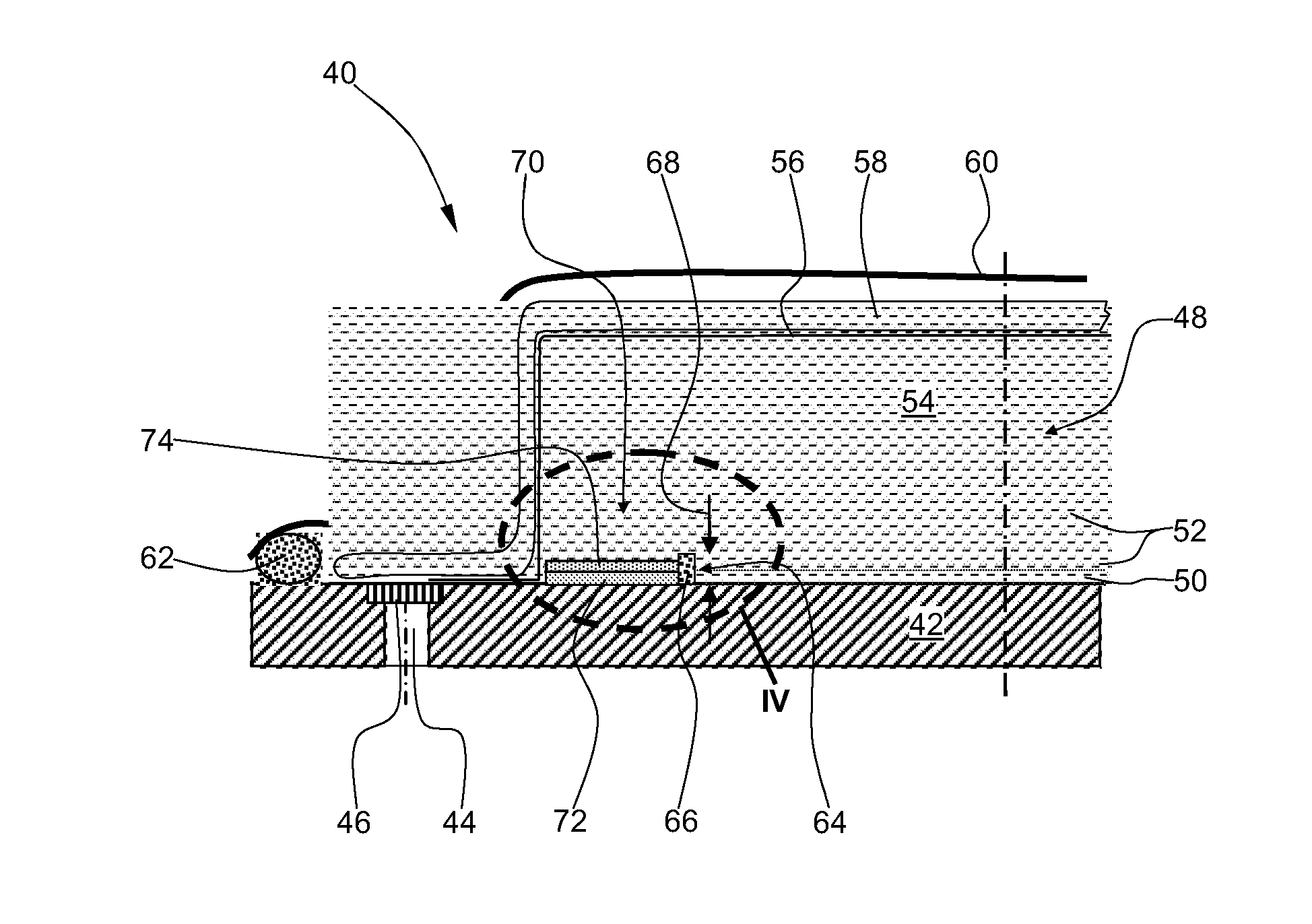
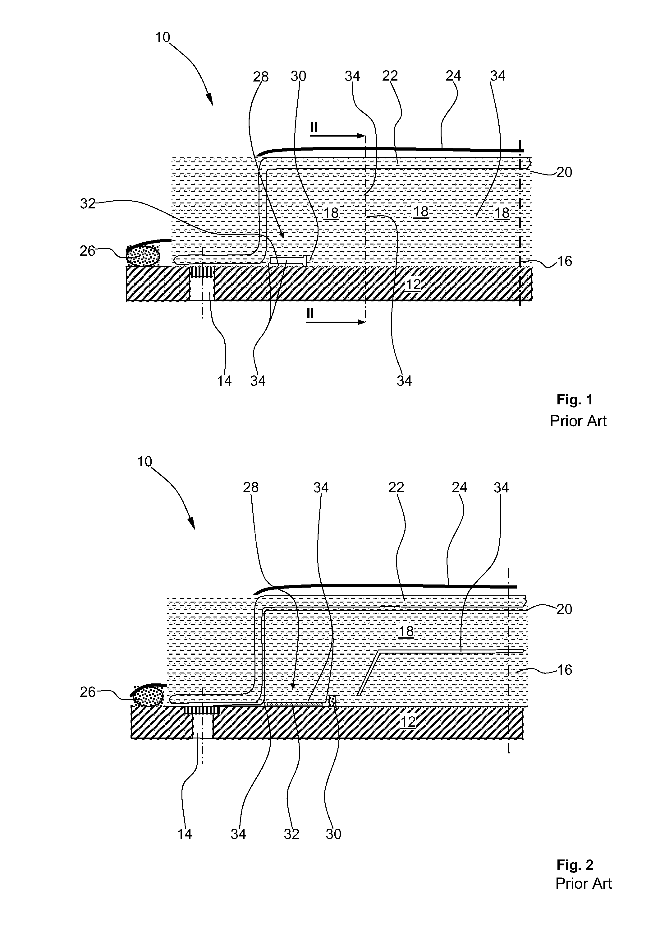
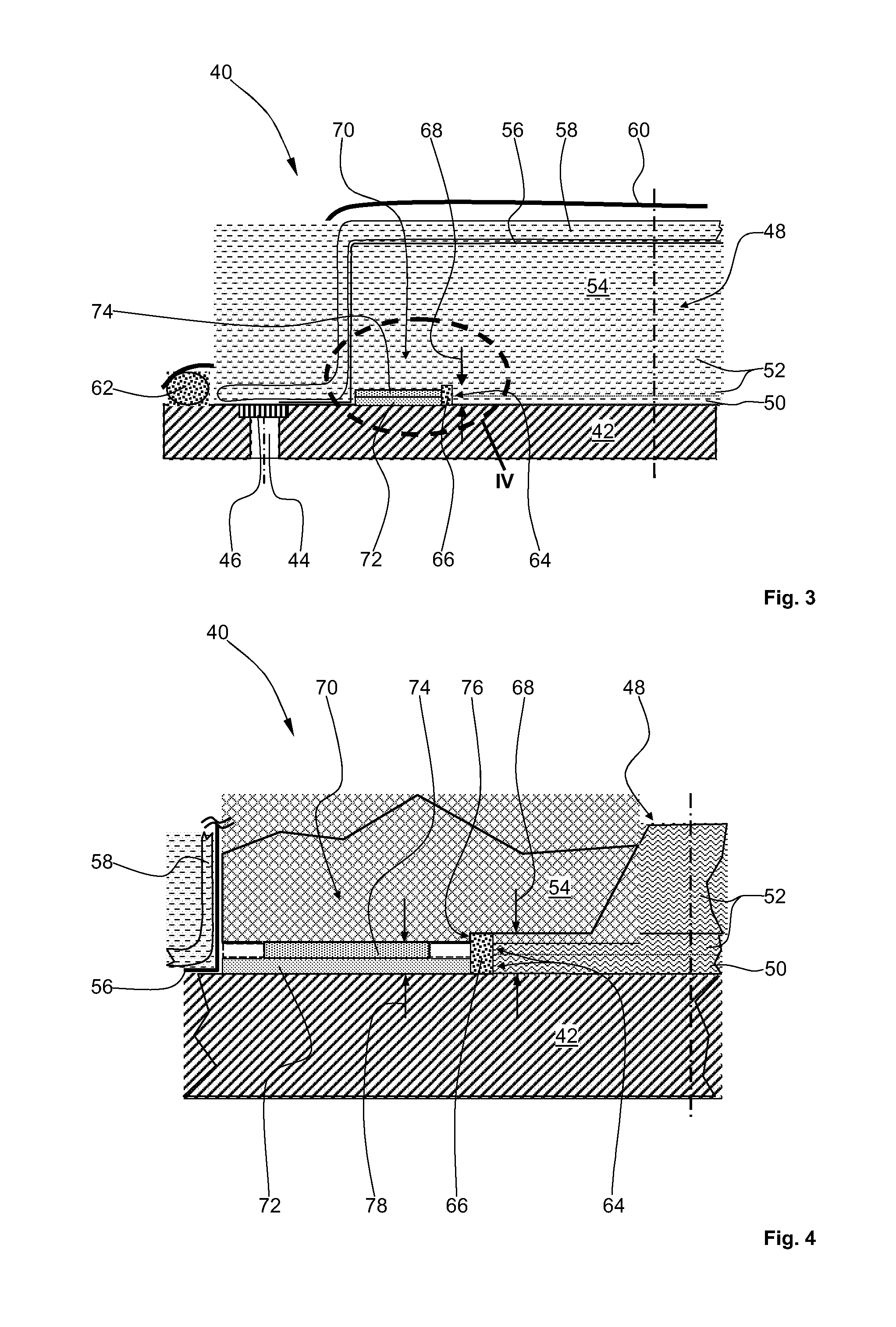
[0033]FIGS. 1 and 2, to which reference is made at the same time in the following description, show a schematic cross-sectional and longitudinal sectional representation of part of an arrangement of prior known art for the manufacture of a bonded component from a fiber-reinforced plastic. FIGS. 1, 2 show only the left-hand part of the symmetrical arrangement in each case.

[0034]An arrangement 10 comprises, among other items, a base molding tool 12 with at least one vacuum channel 14 arranged therein. On the base molding tool 12 is laid down a bonded component 16 of a fiber-reinforced plastic, which is built up from a base laminate, not designated, and a multiplicity of reinforcement laminates to provide integral reinforcement. On the bonded component 16 are furthermore located a multiplicity of form-defining molding tools 18. The molding tools 18 are provided with a release layer 20, i.e., a release film, which in turn is overlaid with an aeration material 22, which is usually formed...


PUM

PropertyMeasurementUnit
temperatureaaaaaaaaaa
specific strengthsaaaaaaaaaa
stiffnessesaaaaaaaaaa

Abstract

A device and method for the manufacture of a bonded component from fiber-reinforced plastics, with a base molding tool and a molding tool. The bonded component is arranged between the base molding tool and the molding tool. The bonded component has at least one base laminate and at least one reinforcement laminate. The molding tool is covered with an aeration material and with a vacuum envelope. The vacuum envelope is sealed with respect to the base molding tool by means of a seal. At least one matrix material film is arranged underneath at least one molding tool overhang, in at least some regions. Undesirable cavities within the device are primarily filled with material from the matrix material film, so that leakage flows of matrix material from the bonded component reduce during the autoclave process. By this means complex and cost-intensive rework of the bonded component is avoided.

Description

CROSS-REFERENCES TO RELATED APPLICATIONS[0001]This application claims the benefit of the U.S. Provisional Application No. 61 / 512,007, filed on Jul. 27, 2011, and of the German patent application No. 10 2011 079 947.8 filed on Jul. 27, 2011, the entire disclosures of which are incorporated herein by way of reference.BACKGROUND OF THE INVENTION[0002]The invention concerns in the first instance a device for the manufacture of a bonded component with fiber-reinforced plastics, with at least one base molding tool and at least one molding tool, wherein the bonded component is arranged between the base molding tool and the molding tool and the bonded component has at least one base laminate and at least one reinforcement laminate, and the molding tool is covered with an aeration material and with a vacuum envelope, wherein the vacuum envelope is sealed with respect to the base molding tool by means of a seal.[0003]For components in which high specific strengths and stiffnesses are required...

Claims


Application Information

Patent Timeline
Patent Type & Authority Applications(United States)
IPC IPC(8): B29C51/30B29C51/14
CPCB29C70/44B29C70/46B29C70/546B29L2031/001B29C51/303B29K2063/00B29K2307/04B29C51/14
Inventor BARDENHAGEN, HEINZ
Owner AIRBUS OPERATIONS GMBH
Why Eureka
Try Eureka