Contactless charging system and contactless charging method

a charging system and contactless technology, applied in electromagnetic wave systems, transportation and packaging, sustainable buildings, etc., can solve the problems of insufficient transfer of the electromagnetic field formed in the primary coil, affecting product quality, and increasing the price of products, so as to reduce energy waste by unnecessary power consumption, high charging efficiency, and high charging efficiency

Active Publication Date: 2014-10-09
KIM IN PYO
View PDF26 Cites 16 Cited by
  • Summary
  • Abstract
  • Description
  • Claims
  • Application Information

AI Technical Summary

Benefits of technology

[0047]In a contactless charging system and a contactless charging method according to the present invention, charging efficiency of a battery is notified by a method that enables a user to know the charging efficiency and the user is induced to control the position of a secondary coil (receiving unit) relative to a primary coil (transmitting unit) to a position having higher charging efficiency, and as a result, contactless charging of the battery may be executed with high charging efficiency as possible to reduce energy waste by unnecessary power consumption and minimize a problem of heat emission which occurs during a charging process.
[0048]According to the present invention, by using a charging frequency having the same value in the transmitting unit and the receiving unit, which is varied in proportion to the charging efficiency of the battery to acquire the charging efficiency of the battery to be notified to the user, related data need not be transmitted between the transmitting unit and the receiving unit in order to acquire the charging efficiency.
[0049]According to the present invention, by setting charging current to be proportional to the charging efficiency of the battery (charging frequency), it is possible resolve a problem of heat emission caused due to a decrease of the charging efficiency depending on deviation of the secondary coil from a regular position relative to the primary coil.

Problems solved by technology

However, when the charging cover is used, there is inconvenience that the charging cover needs to be additionally provided for the contactless charging of the portable phone.
Further, when the secondary coil is further distant from the primary coil by a predetermined deviation distance (i.e., 20 mm) or more, an electromagnetic field formed in the primary coil cannot be sufficiently transferred to the secondary coil, and as a result, charging is stopped.
The “coil movable contactless charging system” and the “plural coil type contactless charging system” have a problem that a product price is relatively increased due to an increase of the number of components as compared with the “magnet type contactless charging system”.
In particular, the “coil movable contactless charging system” has a limit in restricting a weight of the primary coil in order to reduce a load applied to the stepping motor.
The “plurality coil type contactless charging system” has a problem that the size of the transmitter is excessively increased due to an array structure of the primary coils, while the sizes of the primary coils need to be restricted.
However, the “magnet type contactless charging system” has a problem that although the position of the quantum coil may be maintained to the regular position at relatively low cost, when this is applied to the portable phone, the size and the weight of the portable phone are increased due to addition of the magnet and the applied magnet may cause a misoperation of a magnetic field using device (i.e., a compass, a gyro sensor, and the like) embedded in the portable phone.
When the permanent magnet 215 is to be applied to only the primary coil 214 as described above, magnetic force of the permanent magnet acts on the ferrite 222 having a large area, and as a result, since a deviation of the position of the secondary coil from the position of the primary coil may occur, it is difficult to ensure optimal charging efficiency.
However, in the “variable frequency type”, although the charging efficiency is supplemented by changing the charging frequency and the power, for example, when the secondary coil is positioned at an outermost position within a primary coil chargeable range, the charging efficiency is decreased as compared with maximum charging efficiency by approximately 20% or more and in this case, serious heat emission is caused due to an excessive increase of power applied for supplementing the charging efficiency.
In the known contactless charging system described above, the secondary coil deviates from the regular position relative to the primary coil, but when the secondary coil is within a chargeable range, charging is executed and it is marked that the secondary coil is in charge, and as a result, a user cannot know a state that the charging efficiency is low and heat is emitted and continuously performs charging.
Consequently, unnecessary power consumption may be caused or a safety problem may occur due to the heat emission.
However, since two devices (the charging pad and the portable phone) are separated from each other, an additional wireless communication means for data transmission is required to transfer the power (current or voltage) measured in any one device to the other device, and as a result, calculation of the charging efficiency by the measurement value of the power (voltage or current) is an inefficient and very complicated method.
Moreover, in, for example, a lithium ion (Li-ion) or lithium polymer (Li-Polymer) battery, in order to ensure stability such as preventing the danger of explosion by rapid charging and discharging, when it is considered that charging current introduced into the battery is appropriately controlled in the portable phone (i.e., Trickle Charge, Pre-Charge, Fast Charge, and End of charge) and the charging voltage is also requested to be constantly maintained, calculation of the charging efficiency based on the power (voltage or current) is not easily applied to an actual use environment of the portable phone.

Method used


Image

  • Contactless charging system and contactless charging method
  • Contactless charging system and contactless charging method
  • Contactless charging system and contactless charging method

Examples


Embodiment Construction

Technical Problem

[0035]An object of the present invention is to an electromagnetic induction type contactless charging system which outputs charging efficiency of a battery to enable a user to know the charging efficiency, a user is induced to control the position of a secondary coil relative to a primary coil to a position having higher charging efficiency to charge the battery with higher charging efficiency, thereby reducing unnecessary power consumption and reducing heat emission generated during a charging process.

[0036]Another object of the present invention is to minimize a problem of the heat emission which may occur during the charging process in the electromagnetic induction type contactless charging system.

Technical Solution

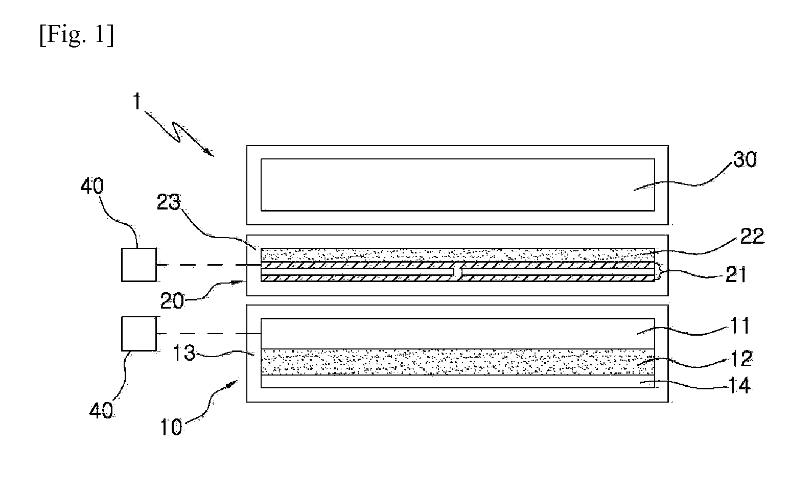
[0037]According to the present invention, provided is a contactless charging system.

[0038]The contactless charging system according to the present invention includes a transmitting unit having a primary coil and a receiving unit having a secondary coil...


PUM


Abstract

A contactless charging method according to the present invention is applied to a contactless charging system 1 which comprises a transmitting unit 10 having a primary coil 11 and a receiving unit 20 having a secondary coil 21 and which charges a battery 30 electrically connected to the secondary coil 21 by the electromagnetic induction generated between the primary coil 11 and the secondary coil 21 and which supplements the charging efficiency of the battery 30 by varying a charging frequency used in the electromagnetic induction in proportion to the charging efficiency of the battery 30 that varies according to the position of the secondary coil 21 relative to the primary coil 11. The contactless charging method comprises: a step of detecting a charging frequency when a charging operation is performed by enabling the primary coil 11 to get close to the secondary coil 21; and a step of outputting the charging efficiency of the battery 30 acquired from the detected charging frequency such that a user may know the charging efficiency.

Description

CROSS-REFERENCE TO RELATED APPLICATION[0001]This application claims the benefit of Korean Patent Application No. 10-2011-0109248, filed on Oct. 25, 2011 and Korean Patent Application No. 10-2011-0116100, filed on Nov. 8, 2011 and Korean Patent Application No. 10-2012-0043508, filed on Apr. 25, 2012 in the Korean Intellectual Property Office, the disclosure of which is incorporated herein by reference.TECHNICAL FIELD[0002]The present invention relates to an electromagnetic induction type contactless charging system, and more particularly, to an electromagnetic induction type contactless charging system suitable for a portable device and a contactless charging method applied thereto.BACKGROUND ART[0003]A battery for supplying power is required to operate various types of portable devices including a portable phone and a charging type battery is widely used as the battery. Wired (contact) charging is typically applied to the charging type battery, but in recent years, contactless (wire...

Claims


Application Information

Patent Timeline
Patent Type & Authority Applications(United States)
IPC IPC(8): H02J7/02H02J7/00
CPCH02J7/04H02J7/025H02J7/0042H02J17/00H02J50/80H02J50/10H02J7/007Y02B40/00
Inventor KIM, SEON SEOB
Owner KIM IN PYO
Why Eureka
Try Eureka