
System and method for manufacturing magnetic resonance imaging gradient coil assemblies

a technology of magnetic resonance imaging and gradient coils, which is applied in the direction of mechanical vibration separation, instruments, vacuum evaporation coating, etc., can solve the problems of weak points in the coil assembly, and affecting the durability of the gradient coil

Active Publication Date: 2014-10-09
GENERAL ELECTRIC CO
View PDF6 Cites 19 Cited by
  • Summary
  • Abstract
  • Description
  • Claims
  • Application Information

AI Technical Summary

Benefits of technology

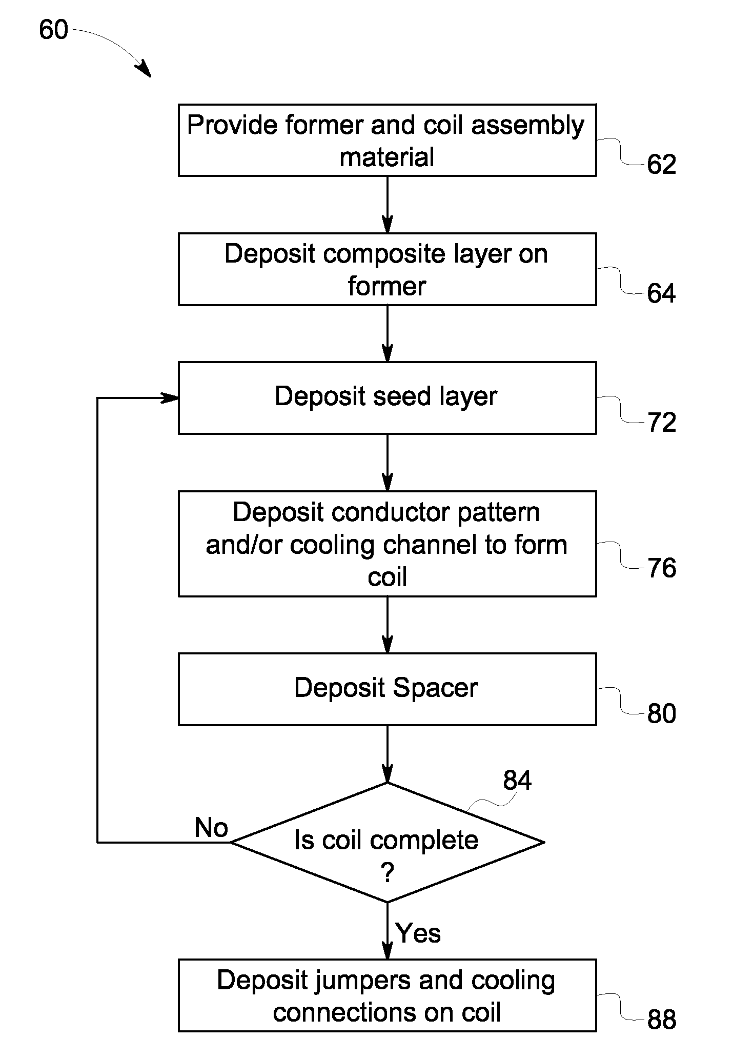
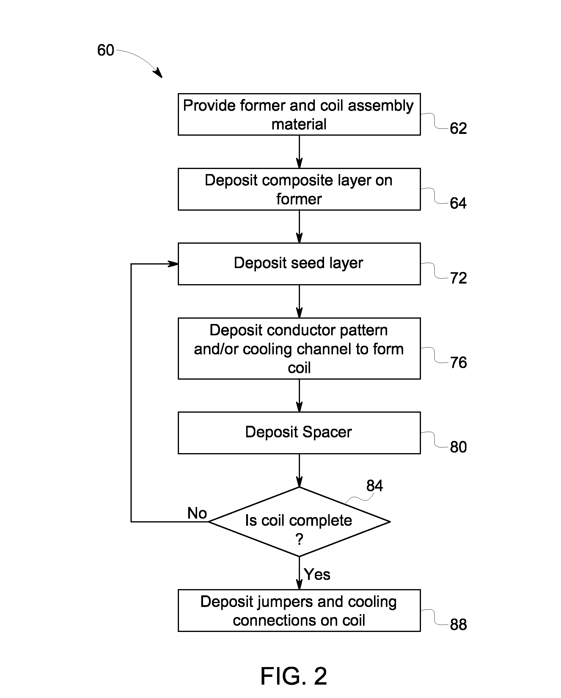
This patent describes a method and system for manufacturing a gradient coil assembly for a magnetic resonance imaging system using additive manufacturing. The method involves depositing layers of materials onto a surface to form the assembly, with the second layer enabling bonding with a conductor material. A consolidation process is used to create the gradient coil using the third layer. The system includes an inductor with internal fluid paths and a quality inspection module that provides feedback to a controller, which adjusts the manufacturing process based on the feedback. The technical effects of this patent include improved accuracy and efficiency in the production of gradient coils for magnetic resonance imaging systems.

Problems solved by technology

In addition, the manner in which the gradient coils are formed may affect their durability.
For example, the durability of the gradient coils may decrease due to stress resulting from winding or otherwise bending the coils to a desired shape.
Furthermore, additional gradient coil features (e.g. soldering pads, connecting leads, jumpers and barbs) are brazed onto the MRI gradient boards, which can introduce weak points into the coil assembly.
Unfortunately, many of the above processes may be performed by hand, which can introduce manufacturer error and uncertainty into the overall manufacturing process.

Method used


Image

  • System and method for manufacturing magnetic resonance imaging gradient coil assemblies
  • System and method for manufacturing magnetic resonance imaging gradient coil assemblies
  • System and method for manufacturing magnetic resonance imaging gradient coil assemblies

Examples


Embodiment Construction

[0019]One or more specific embodiments will be described below. In an effort to provide a concise description of these embodiments, all features of an actual implementation may not be described in the specification. It should be appreciated that in the development of any such actual implementation, as in any engineering or design project, numerous implementation-specific decisions must be made to achieve the developers' specific goals, such as compliance with system-related and business-related constraints, which may vary from one implementation to another. Moreover, it should be appreciated that such a development effort might be complex and time consuming, but would nevertheless be a routine undertaking of design, fabrication, and manufacture for those of ordinary skill having the benefit of this disclosure.

[0020]When introducing elements of various embodiments of the present invention, the articles “a,”“an,”“the,” and “said” are intended to mean that there are one or more of the ...


PUM

PropertyMeasurementUnit
Dielectric polarization enthalpyaaaaaaaaaa
Structureaaaaaaaaaa
Currentaaaaaaaaaa

Abstract

The embodiments disclosed herein relate generally to magnetic resonance imaging systems and, more specifically, to the manufacturing of a gradient coil assembly for magnetic resonance imaging (MRI) systems. For example, in one embodiment, a method of manufacturing a gradient coil assembly for a magnetic resonance imaging system includes depositing a first layer comprising a base material onto a surface to form a substrate and depositing a second layer onto the first layer. The second layer may enable bonding between a conductor material and the substrate. The method also includes depositing a third layer onto the second layer using a consolidation process. The consolidation process uses the conductor material to form at least a portion of a gradient coil.

Description

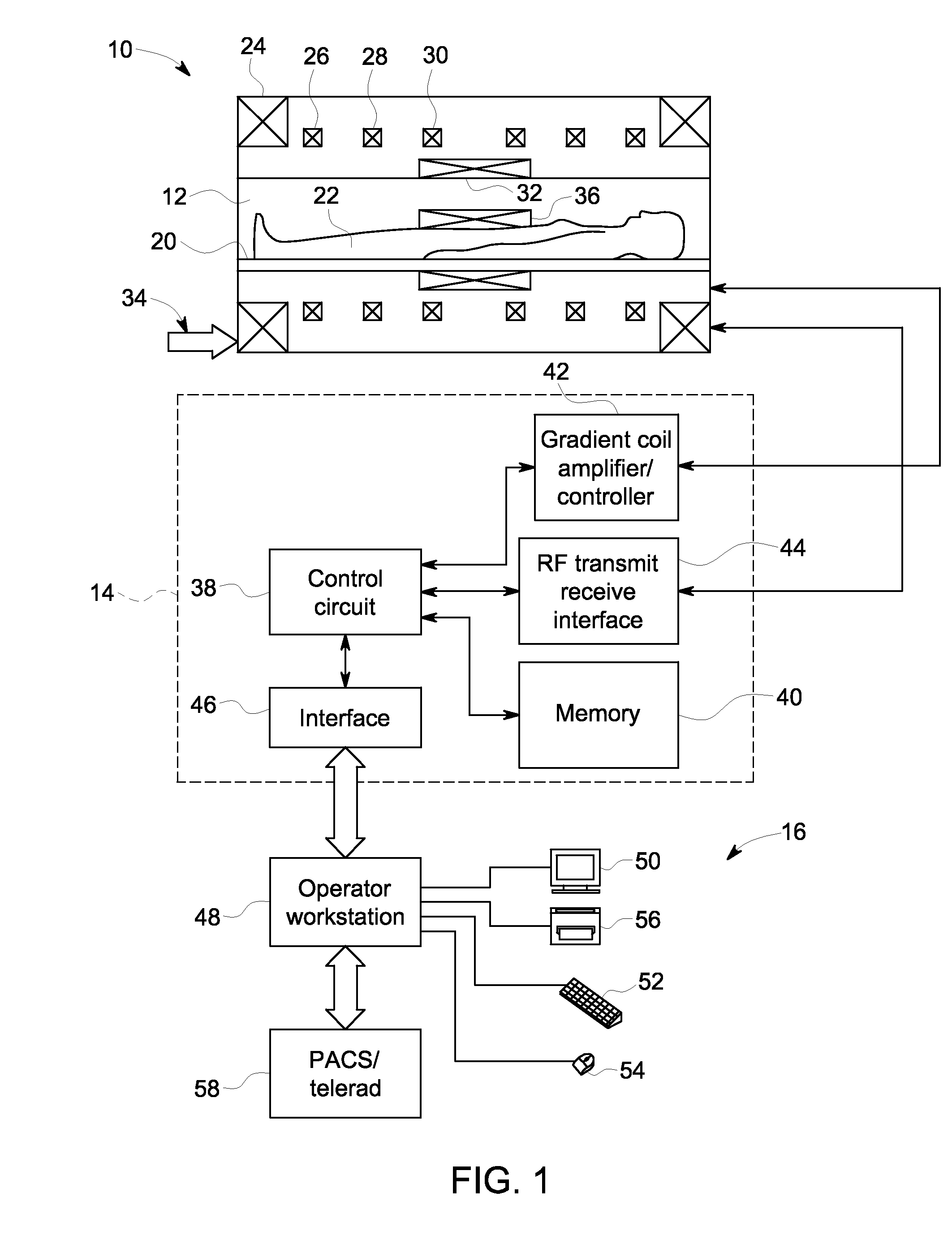
BACKGROUND[0001]This section is intended to introduce the reader to various aspects of art that may be related to various aspects of the present disclosure, which are described and / or claimed below. This discussion is believed to be helpful in providing the reader with background information to facilitate a better understanding of the various aspects of the present disclosure. Accordingly, it should be understood that these statements are to be read in this light, and not as admissions of prior art.[0002]Magnetic Resonance Imaging (MRI) systems enable imaging based on a primary magnetic field, a radio frequency (RF) pulse, and time-varying magnetic gradient fields that interact with specific nuclear components in an object, such as hydrogen nuclei in water molecules. The magnetic moments of such nuclei may generally align with the primary magnetic field, but subsequently precess about the bulk magnetic field direction at a characteristic frequency known as the Larmor frequency. An R...

Claims


Application Information

Patent Timeline
IPC IPC(8): G01R33/38
CPCG01R33/3802G01R33/3856G01R33/3858H01F41/04
Inventor MATHIEU, JEAN-BAPTISTEKURUCAY, SABANFOO, THOMAS KWOK-FAHYANG, YANZHE
Owner GENERAL ELECTRIC CO
Learn More