System and Method for Optimal Cooling by Thermo Electric Cooling Module (TEC) and an Electric Fan Thereof

a technology of thermoelectric cooling module and electric fan, which is applied in the direction of machine operation mode, lighting and heating apparatus, heating type, etc., can solve the problems of not reducing room temperature or providing desirable thermal comfort, adding to the discomfort of occupants, and unable to reduce the room temperature or provide desirable thermal comfort, etc., to facilitate a plurality of calibrations and facilitate adaptive comfort.

Active Publication Date: 2014-10-16
ANANDHAKRISHNAN VAIDYANATHAN
View PDF14 Cites 9 Cited by
  • Summary
  • Abstract
  • Description
  • Claims
  • Application Information

AI Technical Summary

Benefits of technology

[0026]According to one embodiment of the present invention, the cold side management module provides a cooling effect by distributing the heat uniformly across a surface of the secondary heat exchanger module as well as a plurality of fins and groves provided in the said system. The cold side management applies a gradient to collect a condensate formed due to condensation of the room air under specific conditions. The cold side management module disposes the collected condensate either through a reverse circulation of the fluid or directly to the ambient environment.
[0027]According to one embodiment of the present invention, the integrated control module facilitates a plurality of calibrations. The plurality of calibrations comprises calculating the ambient and the room air properties, setting a plurality of indoor performance parameters to facilitate an adaptive comfort and powering the said system with either an alternate current or a direct current with varying voltages and currents.

Problems solved by technology

The movement of air at a reasonable speed provides thermal relief to some extent, but suffer from one disadvantage that they cannot reduce the room temperature or provide desirable thermal comfort.
Thus, the fans re-circulate the high temperature air that makes the indoor environment uncomfortable.
Further, prolonged use of electric fan may keep re-circulating the warm or hot in the room which adds to discomfort of the occupants.
When there is a desire to seek better and enhanced thermal comfort with reduced temperature and dehumidification, air conditioners are used that provide excellent cooling but at the same time are not considered as environment friendly as the compressors use environment impacting CFC (Chloro Fluoro Carbons), that have ODP (Ozone depletion potential) and GWP (global warming potential).
These cause damage to ozonosphere of the earth and leads to greenhouse effect that affect the climatic conditions and eventually affect human beings.
This fluctuation creates wide temperature swings inside the room.
It is widely known that the inside temperatures that are substantially lower than ambient temperatures prevalent outside could cause thermal shocks for occupants when they move in and out of the conditioned room.
Apart from that the air conditioners are also expensive and are energy intensive that require substantially high power (an air conditioner requires about 1000 watts / hr per TR) which causes a huge load on the grid power and cannot be afforded by most of the people.
In several regions there is no continued supply of grid power.
Hence, a combination of non availability of regular power supply, high energy bills per month makes air conditioner unaffordable to most of the people.
However, a major limitation that exists in the prior arts is that the air is sucked across the water absorbing curtain and the equipment functions like an evaporative cooling system or air cooler or a swamp cooler when air is drawn across different media.
Moreover, the dirt of the incoming air contaminates the water and lends to undesirable foul smell, bacteria formation in water and causes severe health hazards to the occupants.
In the other case, cooling system does not provide a condensate drain system and hence the condensate will drip on the floor or condensate particles may be sprayed on the occupants like a water shower.
Further the limitations lies in the conventional cooling systems that they provide only temperature reduction, without a humidity control and are unable to differentiate between various seasons in a particular geographical region.

Method used


Image

  • System and Method for Optimal Cooling by Thermo Electric Cooling Module (TEC) and an Electric Fan Thereof
  • System and Method for Optimal Cooling by Thermo Electric Cooling Module (TEC) and an Electric Fan Thereof
  • System and Method for Optimal Cooling by Thermo Electric Cooling Module (TEC) and an Electric Fan Thereof

Examples


Embodiment Construction

[0044]In the following detailed description, a reference is made to the accompanying drawings that form a part hereof, and in which the specific embodiments that may be practiced is shown by way of illustration. The embodiments are described in sufficient detail to enable those skilled in the art to practice the embodiments and it is to be understood that the logical, mechanical and other changes may be made without departing from the scope of the embodiments. The following detailed description is therefore not to be taken in a limiting sense.

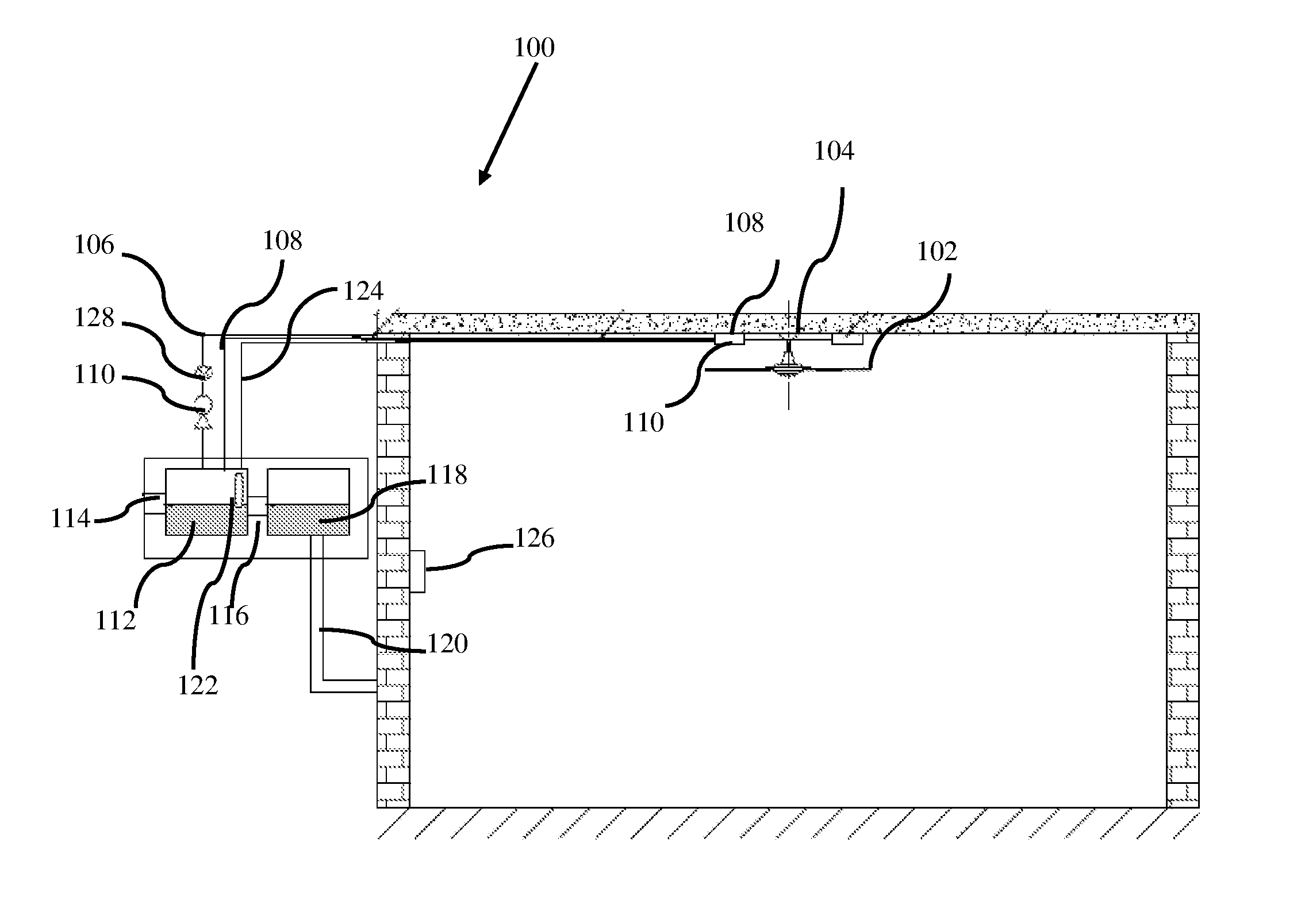
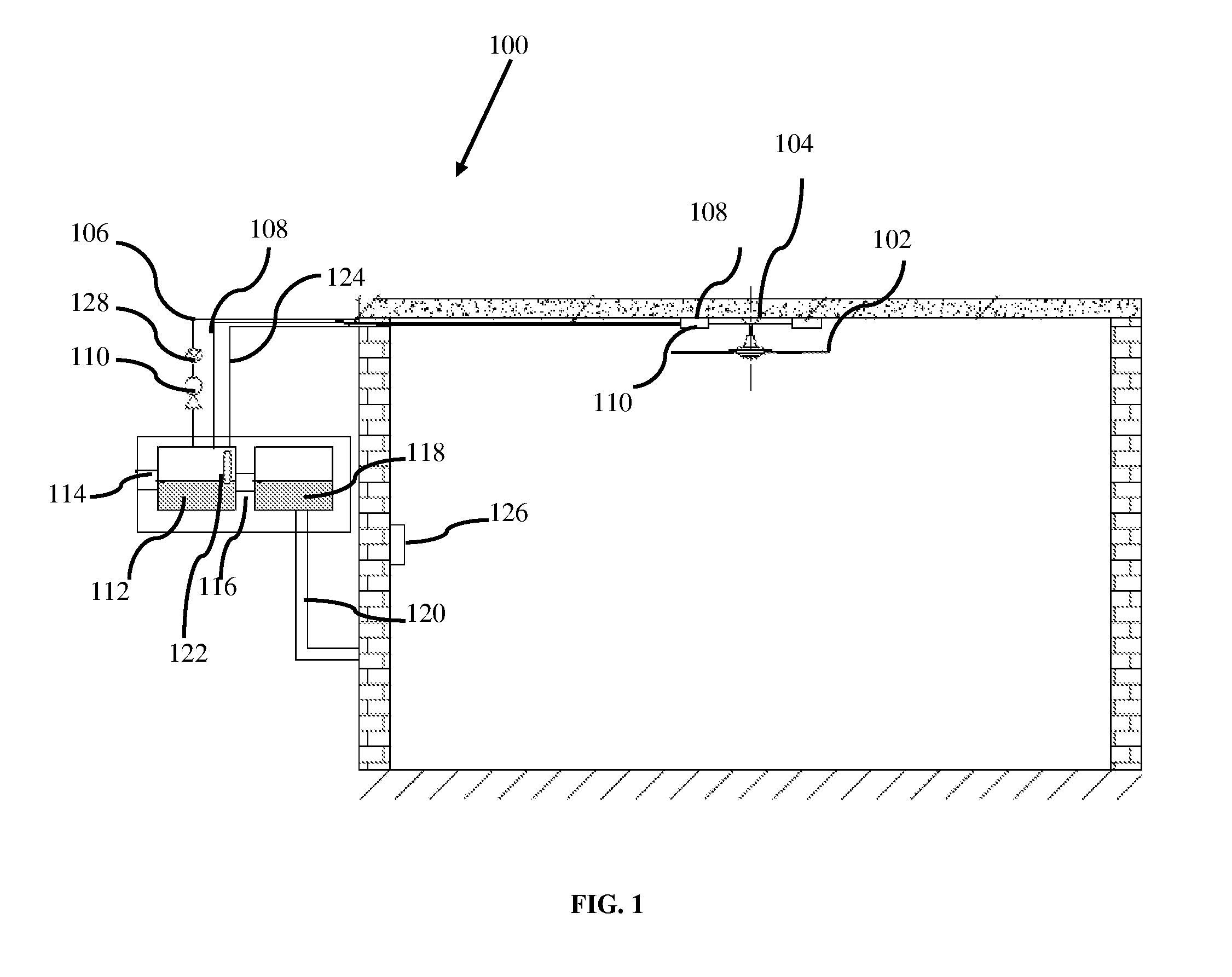
[0045]FIG. 1 illustrates a sectional view of the cooling system incorporated with TEC and ceiling fan, according to one embodiment of the present invention. With respect to FIG. 1, the said system comprises the thermoelectric cooling module (100) which is fitted with a grouting plate (104).

[0046]According to one embodiment of the present invention, the thermoelectric cooling module (100) is provided with the hot side management module 108 and t...


PUM


Abstract

The various embodiments of the present system disclose a system for an optimal cooling by a thermoelectric cooling module and an electric fan thereof. The system comprises a thermoelectric cooling module, an electric fan and a housing. The thermoelectric cooling module comprises a plurality of thermoelectric sub-modules, a hot side management module, a cold side management module and an integrated control module. The present invention provides an optimal cooling on the basis of an external weather condition. The present invention further provides an optimal cooling by implementing an efficient fluid circulation mechanism. The present invention also provides a dynamic management over the working of various modules of the said system.

Description

A) TECHNICAL FIELD OF INVENTION[0001]The present invention generally relates to an electronic system along with an electromechanical device for a closed space and particularly relates to a system and a method for providing on an adaptive comfort for the occupants of the closed space. The present invention more particularly relates to a system and a method for providing an effective and efficient cooling management mechanism on the basis of an ambient weather condition.B) BACKGROUND OF INVENTION[0002]Traditionally the electric fans are used to provide a thermal relief for the occupants in a habitable closed space such as a room. Generally an electric fan re-circulates the room air at different velocities which varies between 300 to 800 rpm (1.5 m / s to 4 m / s) as the terminal velocity at the outlets or the fan blades. These fans typically consume less power (40 to 80 watts per hour). The movement of air at a reasonable speed provides thermal relief to some extent, but suffer from one d...

Claims


Application Information

Patent Timeline
Patent Type & Authority Applications(United States)
IPC IPC(8): F25B21/02
CPCF25B21/02H01L35/30F24F5/0042H10N10/13
Inventor ANANDHAKRISHNAN, VAIDYANATHAN
Owner ANANDHAKRISHNAN VAIDYANATHAN
Why Eureka
Try Eureka