Concrete slab forming apparatus

a technology of concrete slabs and forming equipment, which is applied in the direction of manufacturing tools, foundry moulding equipment, foundry patterns, etc., can solve the problems of unthreaded rebars that contribute nothing to the location of steel plates, and may or may not pass unthreaded bars, so as to keep the cost of forms low

Active Publication Date: 2014-10-16
DRYBURGH RICHARD J +2
View PDF38 Cites 19 Cited by
  • Summary
  • Abstract
  • Description
  • Claims
  • Application Information

AI Technical Summary

Benefits of technology

[0005]This invention uses a permanent steel form which is held in the desired shape by the stiffness of the steel forms, which when coupled with the special threaded reinforcing bars (rebars) which extend across the form (in both directions) and through holes provided in the sheet steel forms (end plates and side plates) to hold the form sections of the form secure. Of course special nuts are threaded on to the ends of the threaded rebars. To help keep the cost of the form to a low value, unthreaded rebars are interspersed at intervals between the threaded rebars. It is understood however, that these unthreaded bars may or may not pass through apertures in the steel plates which are used to surround the concrete slab. In any event, these unthreaded rebars contribute nothing to the location of the steel plates surrounding the concrete slab.

Problems solved by technology

It is understood however, that these unthreaded bars may or may not pass through apertures in the steel plates which are used to surround the concrete slab.
In any event, these unthreaded rebars contribute nothing to the location of the steel plates surrounding the concrete slab.

Method used


Image

  • Concrete slab forming apparatus
  • Concrete slab forming apparatus
  • Concrete slab forming apparatus

Examples


Embodiment Construction

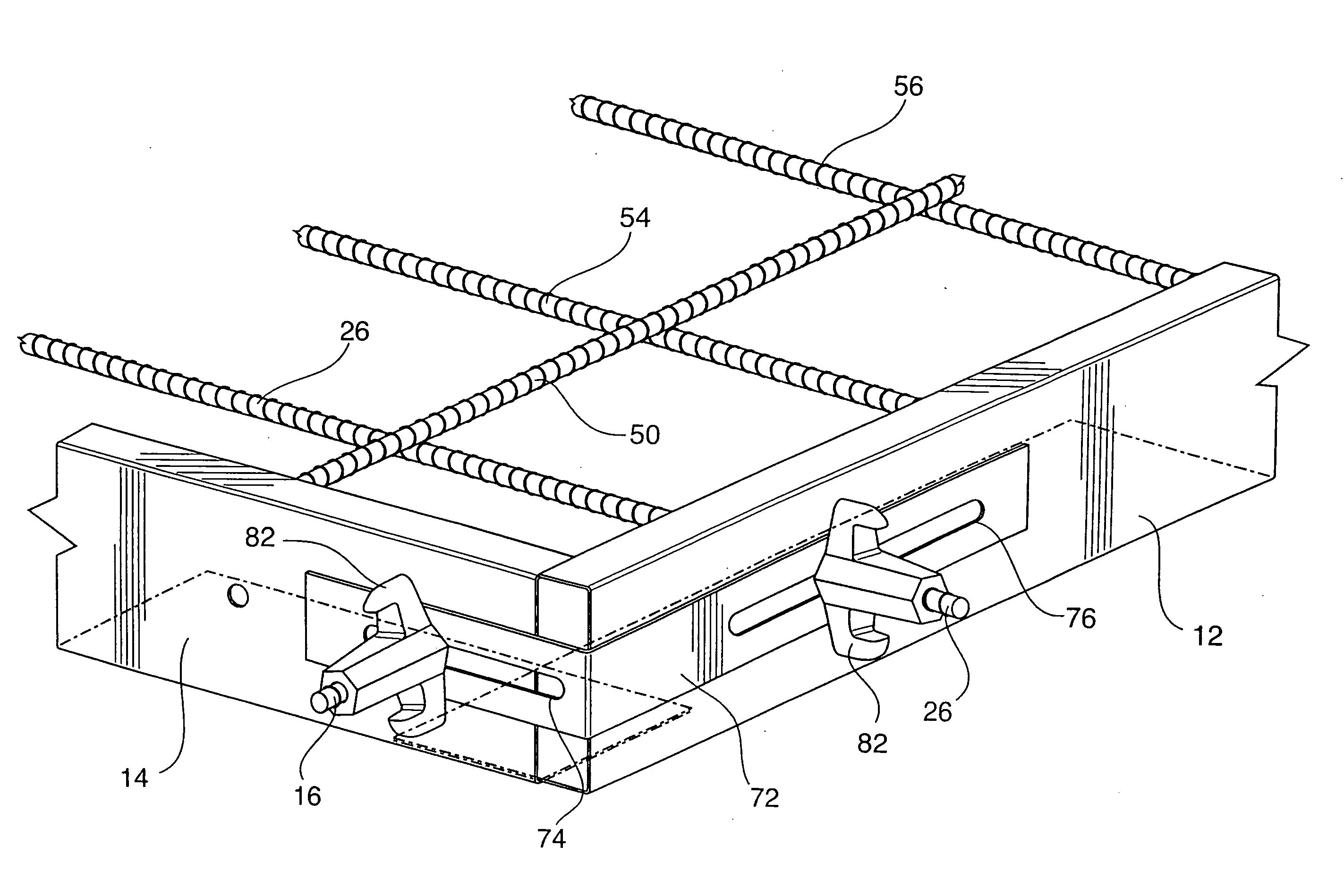
[0012]In order to successfully design the slab of this invention it will be found that several of the values that are used in association with this invention have been predetermined beforehand. For instance the thickness of the slab normally will be specified by the designer of the slab. In no event will the thickness of the slab be less than four inches and greater than eight inches. Generally the thickness will be dictated by the National Building Code and / or by the Building Code in the area in which the slab is to be located.

[0013]The concrete form generally uses a steel form that has a vertical height of about six inches. This is a matter for the Designer of the form to decide. As soon as the Designer has determined the thickness of the Concrete Slab will be, he is ready to specify the vertical height of the steel framework. which will surround the concrete slab.

[0014]Any adjustment to the thickness is done using a foamed styro-foamed material known as “SM” which may be placed i...


PUM

PropertyMeasurementUnit
thicknessaaaaaaaaaa
thicknessaaaaaaaaaa
vertical heightaaaaaaaaaa

Abstract

A form for a concrete slab which consists of a series of similarly shaped steel plates that are held in predetermined spaced relationship by a series of special rebars, (special nuts are provided) before the slab is poured. The slab is criss-crossed by rebars which extend through the form to accurately locate the remaining steel plates as well as to prevent excessive cracking of the slab.

Description

BACKGROUND OF THE INVENTION[0001]Concrete slabs have been manufactured over the past years using a variety of forms and materials. The Romans first used a slab composition composed of quick lime, pozzolana and a kind of pumice which is now known as Roman Concrete and this freed the Romans from the use of brick and stone in building structures. This substance was subjected to change and improvement until we have what is now known as modern concrete which is composed of Portland Cement (a powder) and a variety of aggregates to fill a variety of needs.[0002]One question has always been with us, and that is “how do we increase the tensile strength of the cured concrete?” The present answer is the use of specially made steel rods (rebars) embedded in the concrete as it cured and this gives the necessary tensile strength to the cured concrete. It is known to use other materials such as fibres, steel shavings and materials such as horse hair which when added to the concrete mix improve its...

Claims


Application Information

Patent Timeline
Patent Type & Authority Applications(United States)
IPC IPC(8): E04G11/36
CPCE04G11/36E04C2/06E04C2/384B28B7/0014B22C9/064E04C2/50E04C2/044
Inventor DRYBURGH, RICHARD J.MAUGHAN, MICHAEL H.BRADLEY, GRAEME A.
Owner DRYBURGH RICHARD J
Why Eureka
Try Eureka