High density electrode structure

a high-density electrode and electrode technology, applied in the field of cabling, can solve the problem of limiting the extent to which the catheter diameter may be reduced

Active Publication Date: 2014-10-16
BIOSENSE WEBSTER (ISRAEL) LTD
View PDF21 Cites 77 Cited by
  • Summary
  • Abstract
  • Description
  • Claims
  • Application Information

AI Technical Summary

Problems solved by technology

On the other hand, the catheter is normally used to deliver entities, such as sensors or electrodes, to an internal organ of the patient, and these entities, and their associated wiring, may limit the extent to which the catheter diameter may be reduced.

Method used


Image

  • High density electrode structure
  • High density electrode structure
  • High density electrode structure

Examples


Embodiment Construction

Overview

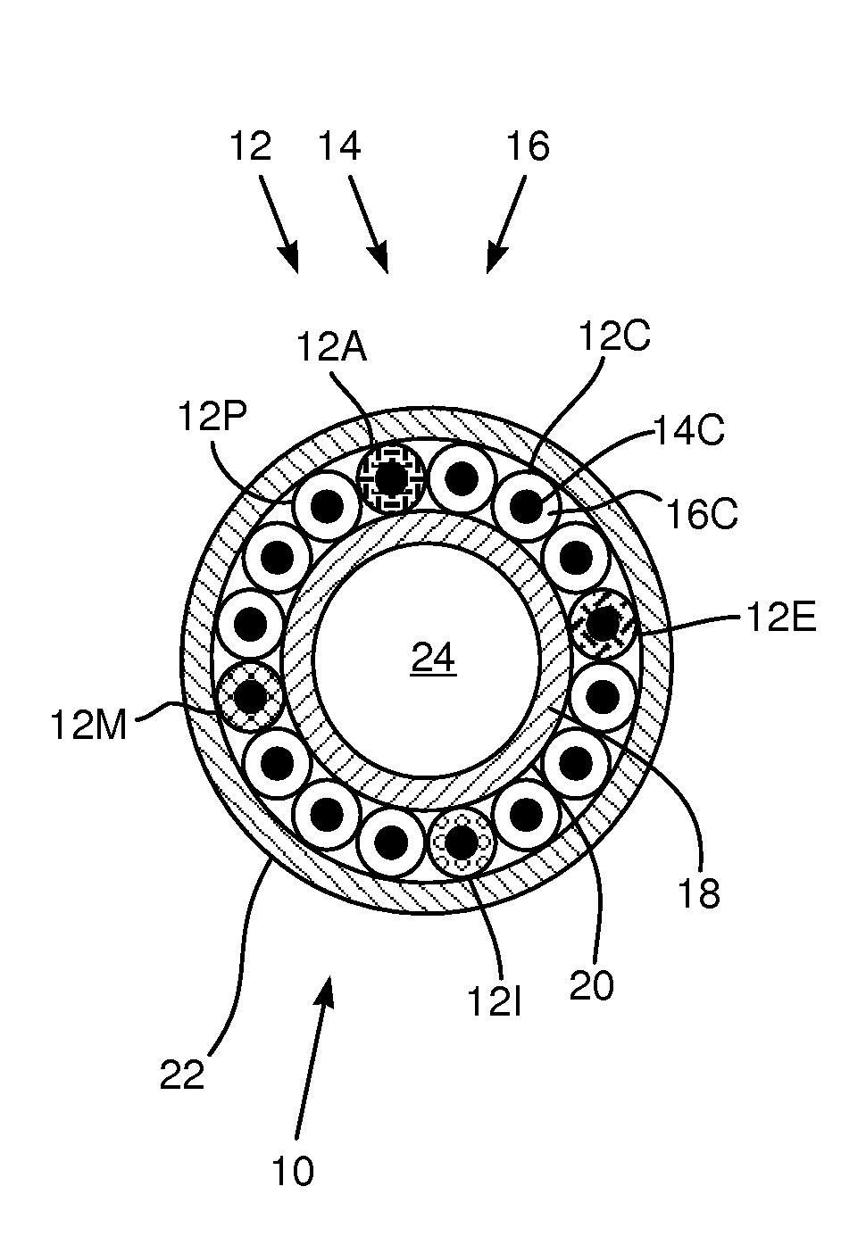
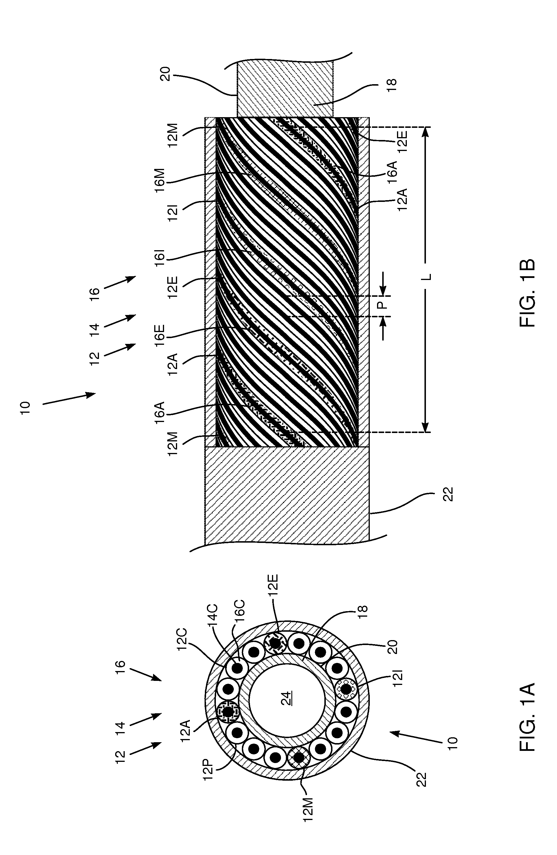
[0065]An embodiment of the present invention provides cabling to which a high density of electrodes may be attached, the cabling and electrodes typically being used as part of a medical catheter. The cabling comprises insulated wires which are coiled around a core in an arrangement that is topologically equivalent to a multi-start thread configuration. Thus, assuming there are n wires, where n is an integer greater than one, the n wires are coiled in an arrangement topologically equivalent to an n-start thread configuration.

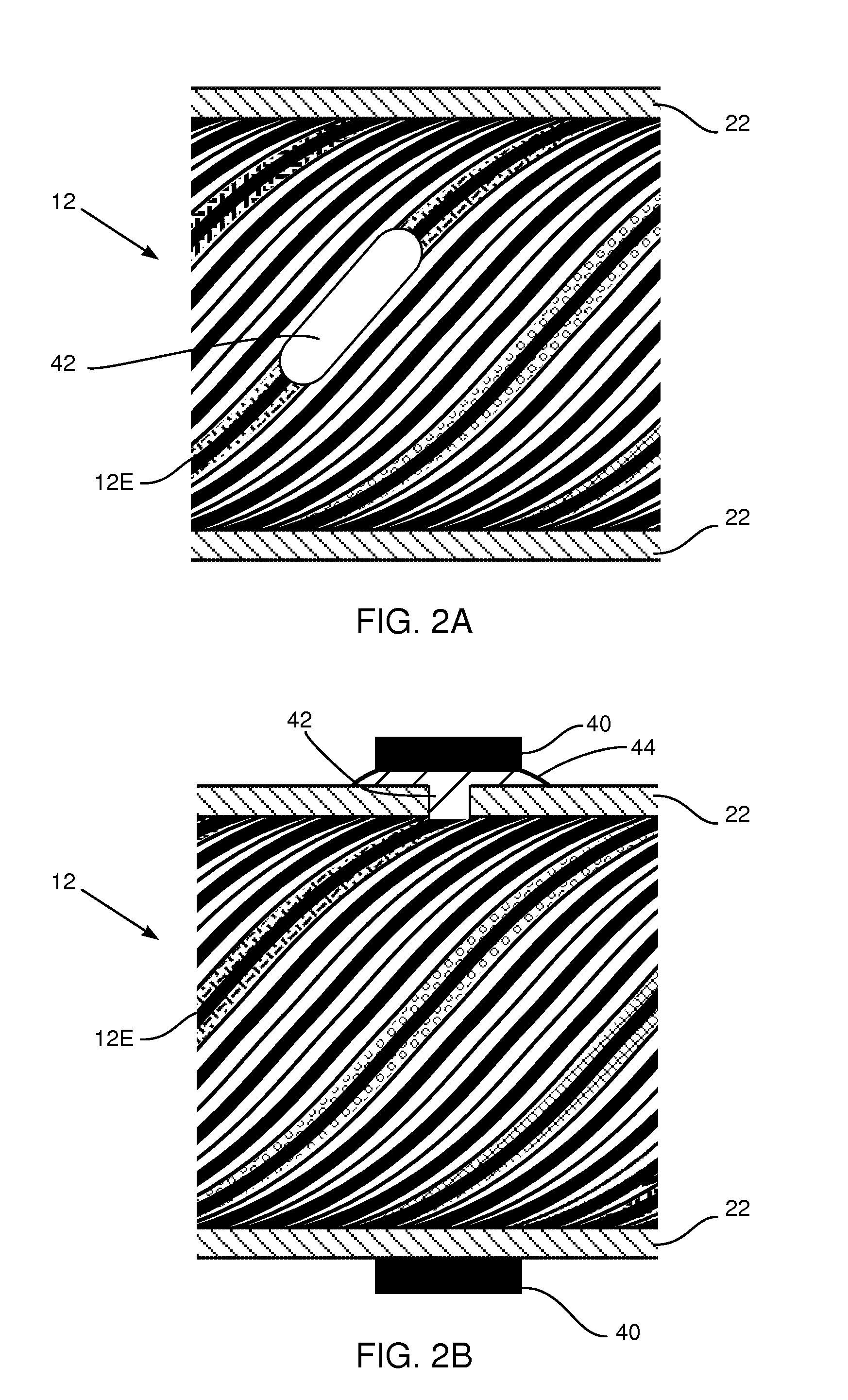
[0066]A sheath covers the n wires, and up to n electrodes may be attached through the sheath to different respective wires.

[0067]Typically the core is a plastic cylindrical tube, in which case the n wires may be coiled on the core in the n-start thread configuration.

[0068]Forming cabling by coiling n wires around a core, in the arrangement described above, permits the diameter of the cabling to be minimized. While the diameter is minimal, the arrangement ...


PUM

PropertyMeasurementUnit
outer diameteraaaaaaaaaa
diameteraaaaaaaaaa

Abstract

Electrode cabling, including a core and n wires coiled on the core in an arrangement topologically equivalent to an n-start thread configuration, wherein n is an integer greater than one. The cabling also includes a sheath covering the n wires and an electrode attached through the sheath to a given wire selected from the n wires.

Description

FIELD OF THE INVENTION[0001]The present invention relates generally to cabling, and specifically to cabling having conductors built into the cabling.BACKGROUND OF THE INVENTION[0002]A medical catheter, when used invasively on a patient, is an example of a probe where the outside diameter of the catheter is a critical measurement. In general, the smaller the diameter of the catheter, the better. On the other hand, the catheter is normally used to deliver entities, such as sensors or electrodes, to an internal organ of the patient, and these entities, and their associated wiring, may limit the extent to which the catheter diameter may be reduced.[0003]A system which enables reduction in the diameter of a catheter, while allowing large numbers of entities such as sensors or electrodes to be incorporated into the catheter, would thus be advantageous.[0004]Documents incorporated by reference in the present patent application are to be considered an integral part of the application except...

Claims


Application Information

Patent Timeline
Patent Type & Authority Applications(United States)
IPC IPC(8): A61B18/14H01B13/00G02B6/44G02B6/04
CPCA61B18/1492H01B13/0036A61B2018/00178G02B6/449G02B6/04H01B7/009A61B5/6858A61B2017/00526A61B2018/0016A61B2018/00267A61B2562/125A61B2562/222A61N1/05A61N1/056H01B13/06Y10T29/49169Y10T29/49174Y10T29/49801A61B5/0084A61B2090/064A61B2018/2294H01B7/048A61B5/6859A61B5/6852A61B5/0538A61B5/287A61B5/318A61M25/09
Inventor GOVARI, ASSAFBEECKLER, CHRISTOPHER THOMASHETTEL, ROWAN OLUND
Owner BIOSENSE WEBSTER (ISRAEL) LTD
Why Eureka
Try Eureka