Electrically heated doc using hcscr cold start NOX controls

a technology of nox control and electric heating, which is applied in the direction of machines/engines, mechanical equipment, surface coverings, etc., can solve the problems of nox reduction or removal, nox removal or reduction, and nox removal or reduction, and achieve the effect of reducing nox in the exhaust gas stream

Inactive Publication Date: 2014-10-23
GM GLOBAL TECH OPERATIONS LLC
View PDF3 Cites 24 Cited by
  • Summary
  • Abstract
  • Description
  • Claims
  • Application Information

AI Technical Summary

Benefits of technology

[0006]In one exemplary embodiment of the invention, an exhaust gas treatment system for an internal combustion engine is provided. The system includes an exhaust gas conduit extending from the engine configured to receive an exhaust gas stream from the engine, a first injector in fluid communication with the exhaust gas conduit configured to selectively inject fuel containing unburned hydrocarbon (HC) into the exhaust gas conduit and an oxidation catalyst disposed in the exhaust gas conduit downstream from the first injector. The system further includes a hydrocarbon selective catalyst reduction (HCSCR) catalyst applied on the oxidation catalyst, a heating device positioned at an upstream side of the oxidation catalyst configured to heat the oxidation catalyst and HCSCR catalyst, a selective catalyst reduction (SCR) device disposed within the exhaust gas conduit downstream from the oxidation catalyst, and a particulate filter positioned downstream from the selective catalyst reduction device.
[0007]In another exemplary embodiment of the invention there is provided a method of operating an exhaust gas treatment system to reduce NOx in an exhaust gas stream during a cold start of an internal combustio

Problems solved by technology

In addition, NOx reduction or removal may occur at the SCR device once the SCR device reaches an adequate operating temperature, typically around 200° C. However, an oxidation catalyst and SCR device do not efficiently oxidize HC and CO, and remove or reduce NOx, respectively, at low temperatures, for example durin

Method used


Image

  • Electrically heated doc using hcscr cold start NOX controls
  • Electrically heated doc using hcscr cold start NOX controls
  • Electrically heated doc using hcscr cold start NOX controls

Examples


Embodiment Construction

[0012]The following description is merely exemplary in nature and is not intended to limit the present disclosure, its application or uses. It should be understood that throughout the drawings, corresponding reference numerals indicate like or corresponding parts and features.

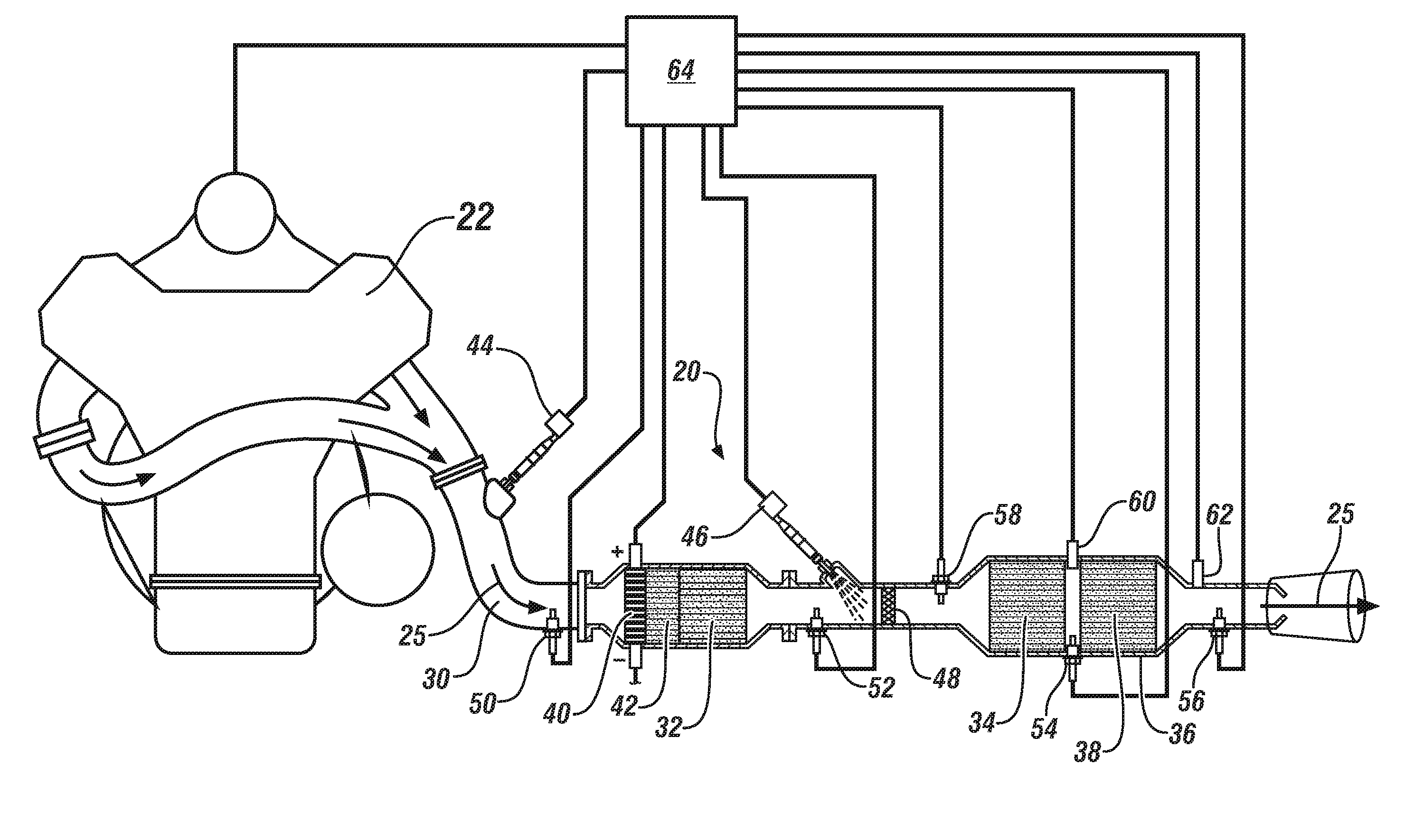
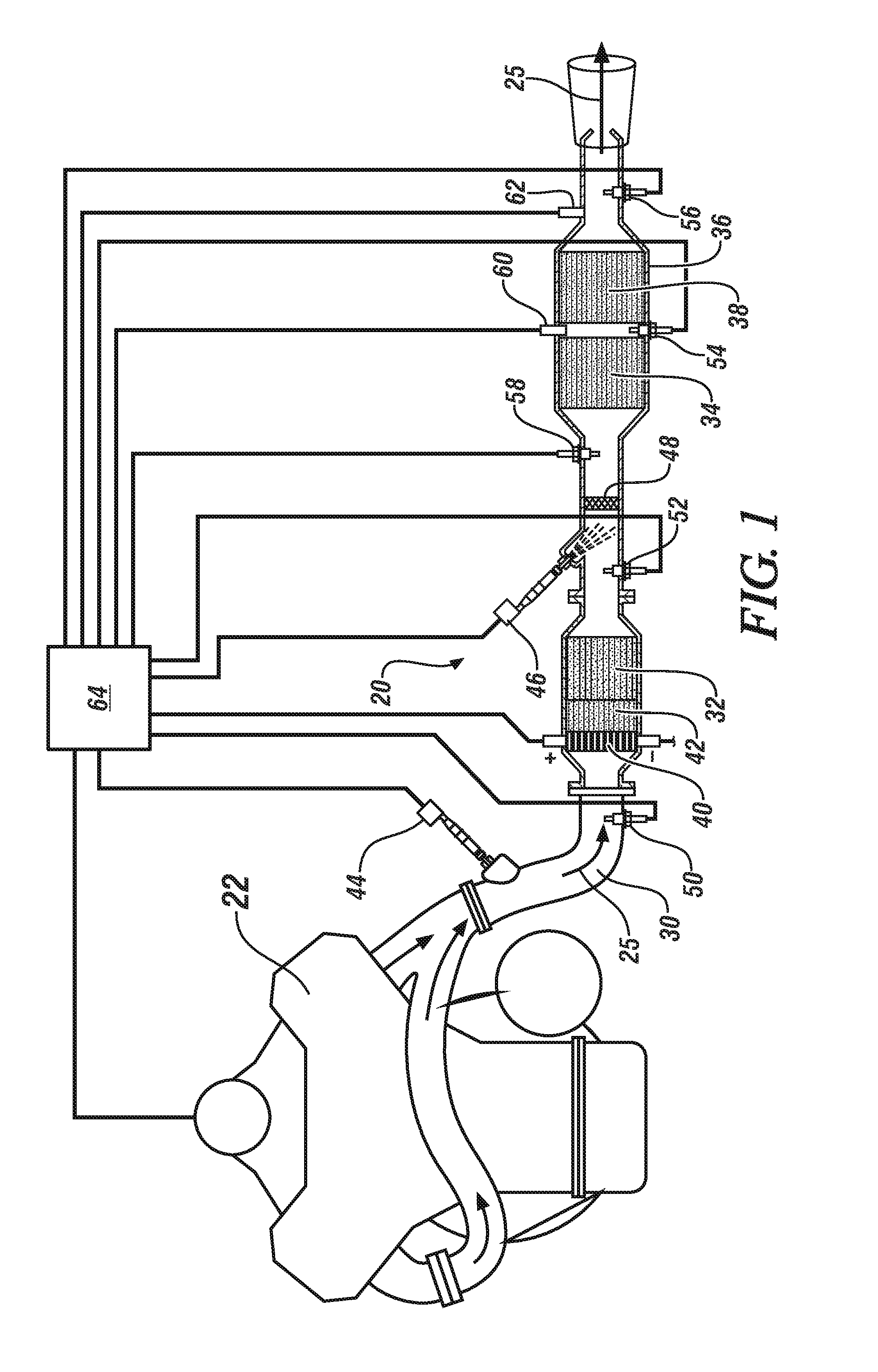
[0013]In accordance with an exemplary embodiment of the subject invention, and with reference to FIG. 1, an exhaust gas treatment system 20 is provided for the reduction of regulated exhaust gas constituents emitted by an internal combustion engine 22. It is understood that the exhaust treatment system 20 described herein may be used in various engine systems utilizing an exhaust gas particulate filter. Such internal combustion engine systems may include, but are not limited to, diesel systems, gasoline systems and various homogeneous charge compression ignition engine systems.

[0014]The exhaust gas treat system 20 includes at least one exhaust gas conduit 30 extending from the engine 22. An exhaust gas stream 2...


PUM


Abstract

An exhaust gas treatment system for an internal combustion engine is provided. The system includes an exhaust gas conduit extending from the engine configured to receive an exhaust gas stream from the engine, a first injector in fluid communication with the exhaust gas conduit configured to selectively inject fuel containing unburned hydrocarbon (HC) into the exhaust gas conduit and an oxidation catalyst disposed in the exhaust gas conduit downstream from the first injector. The system further includes a hydrocarbon selective catalyst reduction (HCSCR) catalyst applied on the oxidation catalyst, a heating device positioned at an upstream side of the oxidation catalyst configured to heat the oxidation catalyst and HCSCR catalyst, a selective catalyst reduction (SCR) device disposed within the exhaust gas conduit downstream from the oxidation catalyst, and a particulate filter positioned downstream from the selective catalyst reduction device.

Description

FIELD OF THE INVENTION[0001]The subject invention relates to an exhaust gas treatment system, and in particular, an exhaust gas treatment system with improved operating characteristics at low temperatures.BACKGROUND[0002]Exhaust gas emitted from an internal combustion engine is a heterogeneous mixture that may contain gaseous emissions such as a carbon monoxide (“CO”), unburned hydrocarbons (“HC”) and oxides of nitrogen (“NOx”) as well as condensed phase materials (liquids and solids) that constitute particulate matter (“PM”). Catalyst compositions typically disposed on catalyst supports or substrates are provided in an engine exhaust system to convert certain, or all of the exhaust constituents into non-regulated exhaust gas components.[0003]In an exhaust treatment technology, there are several known catalyst and filter structures used that have displayed effectiveness in reducing or removing regulated constituents from exhaust gas. For example, an oxidation catalyst may be used to...

Claims


Application Information

Patent Timeline
IPC IPC(8): F01N3/20F01N11/00F01N9/00
CPCF01N3/2013F01N9/00F01N11/002F01N3/103F01N3/36F01N3/035F01N2240/16F01N2510/06F01N2610/02F01N2610/03Y02T10/12
Inventor GONZE, EUGENE V.GOUGH, CHARLES
Owner GM GLOBAL TECH OPERATIONS LLC
Why Eureka
Try Eureka