Oar carrier

a technology for oars and carriers, applied in the direction of rod connections, special-purpose vessels, canoes/kayaks, etc., can solve the problems of oars being expensive, oars being made from carbon fiber composites, oars being often quite unwieldy to handle, etc., to achieve the effect of convenient handling of carriers

Active Publication Date: 2014-10-23
REED TIMOTHY M +1
View PDF7 Cites 10 Cited by
  • Summary
  • Abstract
  • Description
  • Claims
  • Application Information

AI Technical Summary

Benefits of technology

[0018]A still further embodiment of the invention is an oar carrier comprising or including a panel at least partially comprising a resilient material; a plurality of through holes in the panel, each of the plurality of through holes sized to receive a shaft of an oar; and a plurality of slots in a peripheral surface of the panel, each of the plurality of slots providing open access through a minimum width of each of the plurality of slots less than a diameter of the shaft of the oar, wherein a portion of the panel having the minimum width of each of the plurality of slots comprises the resilient material adapted to deflect and allow passage of the shaft of the oar to one of the plurality of through holes. In one aspect, the oar carrier further comprises at least one handle, for example, the handle may comprise a through hole in the panel. In another aspect, at least one of the pluralities of slots may have a geometry different from at least one other of the plurality of slots. The geometry different from at least one other of the plurality of slots may be adapted to facilitate handling of the carrier.

Problems solved by technology

Due to their length, oars can often be quite unwieldy to handle, for example, to carry, or transport to and from the scull or to and from a rowing competition, that is, a regatta.
In addition, oars can be expensive, especially, oars made from carbon fiber composites.
In addition, as suggested by the image shown in FIG. 1, if not damaged during transport or handling, oars can also be exposed to mud or wet grass that can also negatively impact the performance and / or appearance of the oar.
However, the oar display racks shown in FIG. 2 provide little or no remedy to the issues of handling and storing oars that are exemplified by the oar handling and storage issues that characterize the groups of oars shown in FIG. 1.

Method used


Image

  • Oar carrier
  • Oar carrier
  • Oar carrier

Examples


Embodiment Construction

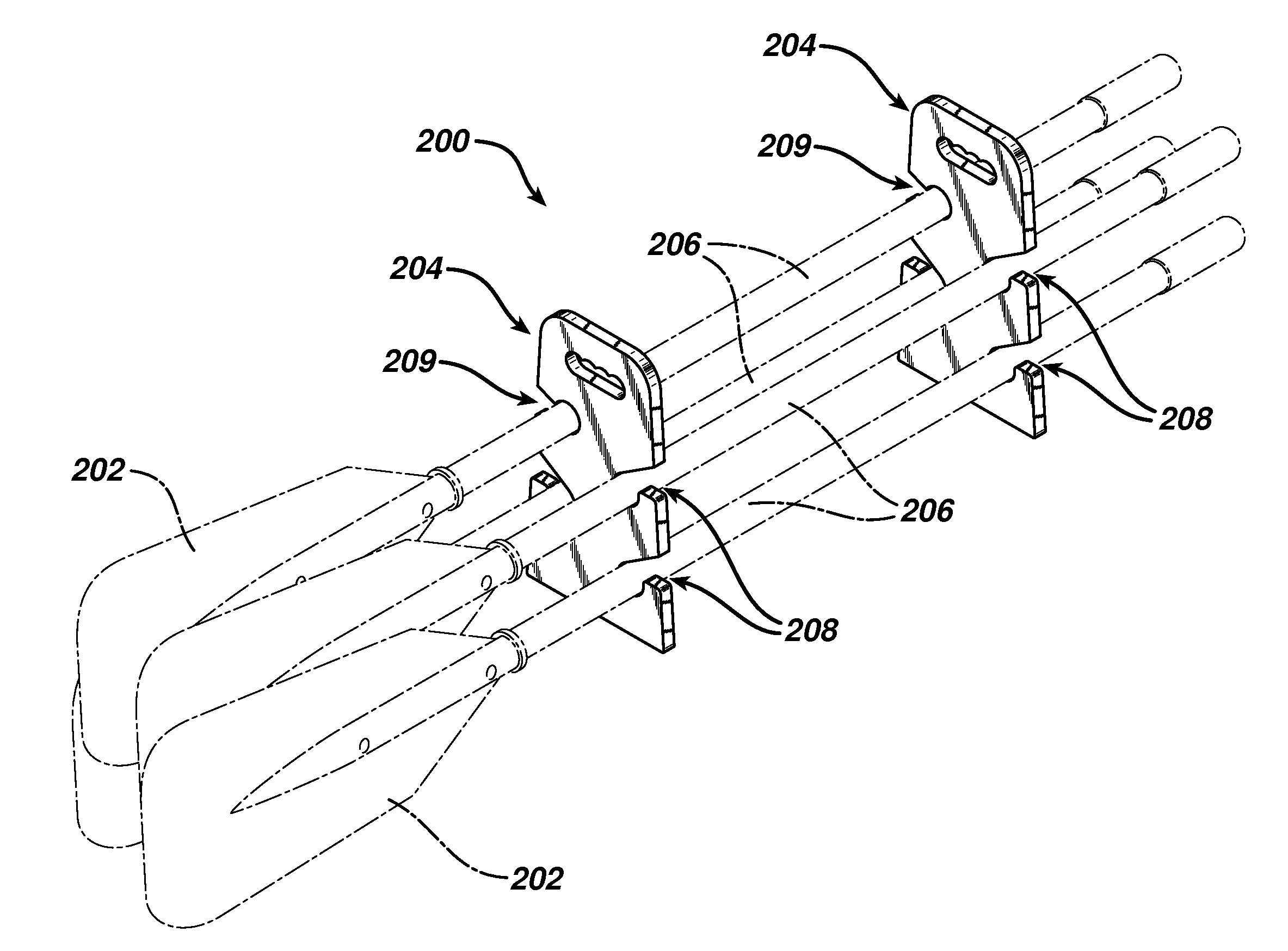
[0042]FIG. 3 is a front perspective view of an assembly 10 of oar carriers 20 and oars 22 (shown partially in phantom) according to one aspect of the present invention. The rear perspective view of assembly 10 is a mirror image of the image shown in FIG. 3. Though two representative oars and two representative oar carriers 20 are shown in FIG. 3, according to aspects of the invention, assembly 10 may include one or more oars 22 and one or more oar carriers 20. Oars 22 may be any oar or paddle, for example, oars 22 may be any oar or paddle used to propel a watercraft, such as, a boat or canoe. However, in one aspect, oars 22 may comprise rowing oars, for example, high performance rowing blades or sculls used by competitive rowing crews, for instance, those marketed by Crocker-USA [http: / / www.crokerusa.com / ], and similar suppliers.

[0043]FIG. 4 is front elevation view of one of the oar carriers 20 shown in FIG. 3. FIG. 5 is a right side elevation view of the oar carrier 20 shown in FIG...


PUM


Abstract

Oar carriers and methods of carrying oars, for example, rowing blades or sculls used by competitive rowing crews. The oar carriers include a panel, through holes in the panel sized to receive a shaft of an oar, and slots in a peripheral surface of the panel providing open access to the through holes to allow transfer of the shaft to the through hole. The slots may have a minimum width less than the diameter of the shaft of an oar, where the slot is made of a resilient material adapted to deflect and allow the diameter of the shaft to transfer to the through hole. One or more handles may be provided to the carrier. Methods of using the oar carrier and arrangements of oars and oar carriers are also disclosed.

Description

CROSS-REFERENCE TO RELATED APPLICATIONS[0001]This application claims priority from pending U.S. Provisional Patent Application 61 / 812,945, filed on Apr. 17, 2013, the disclosure of which is included by reference herein in its entirety.[0002]This application is related to co-pending U.S. Design patent application Ser. 29 / 452,509, filed on Apr. 17, 2013, the disclosure of which is included by reference herein in its entirety.BACKGROUND OF THE INVENTION[0003]1. Technical Field[0004]The present invention generally relates to carriers for rowing oars. More particularly, the present invention relates to carriers for rowing oars having slots adapted to receive the oars and through holes adjoining the slots adapted to receive and retain the oars, for example, for transport or storage.[0005]2. Description of Related Art[0006]In rowing, for example, in competitive rowing, for example, “crew,” the participants propel their watercraft, for example, sculls or shells, with oars. As known in the a...

Claims


Application Information

Patent Timeline
Patent Type & Authority Applications(United States)
IPC IPC(8): F16B7/04
CPCF16B7/0433B63B34/26B63B34/30B63H16/04
Inventor REED, TIMOTHY M.REED, TIMOTHY S.
Owner REED TIMOTHY M
Why Eureka
Try Eureka