Spinal deformity correction instruments and methods

Active Publication Date: 2014-10-23
ALPHATEC SPINE INC
View PDF12 Cites 55 Cited by
  • Summary
  • Abstract
  • Description
  • Claims
  • Application Information

AI Technical Summary

Benefits of technology

[0014]In still other features, the instrument includes a guide portion of the inner member aligned with the slot and configured to prevent deflection as the reduction blade applies the reduction force. In other features, the guid

Problems solved by technology

Various spinal disorders may cause the spine to become misaligned, curved, and/or twisted or result in fractured and/or compressed vertebrae.
Individual correction of each segment can be time-consuming, cumbersome, and potentially difficult to achieve during a surgical procedure.
Often the instrumentati

Method used


Image

  • Spinal deformity correction instruments and methods
  • Spinal deformity correction instruments and methods
  • Spinal deformity correction instruments and methods

Examples


Embodiment Construction

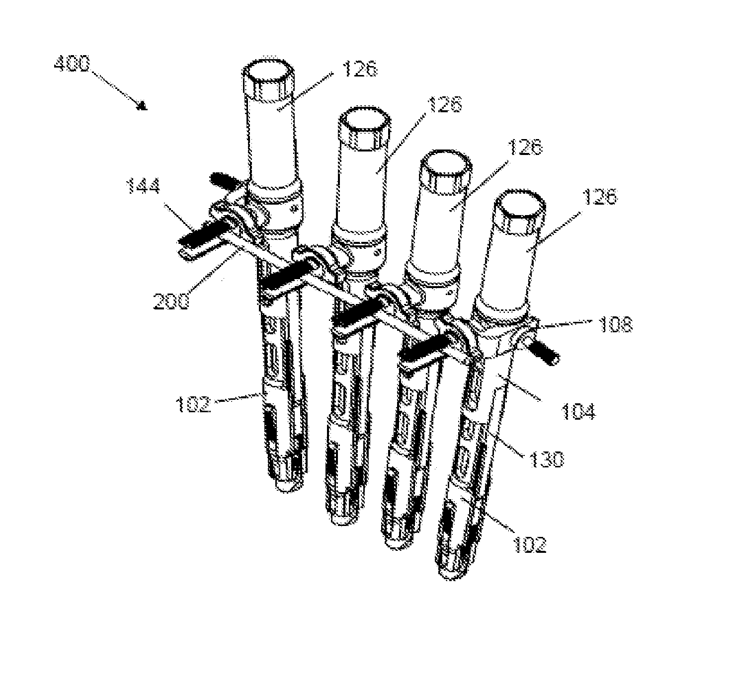
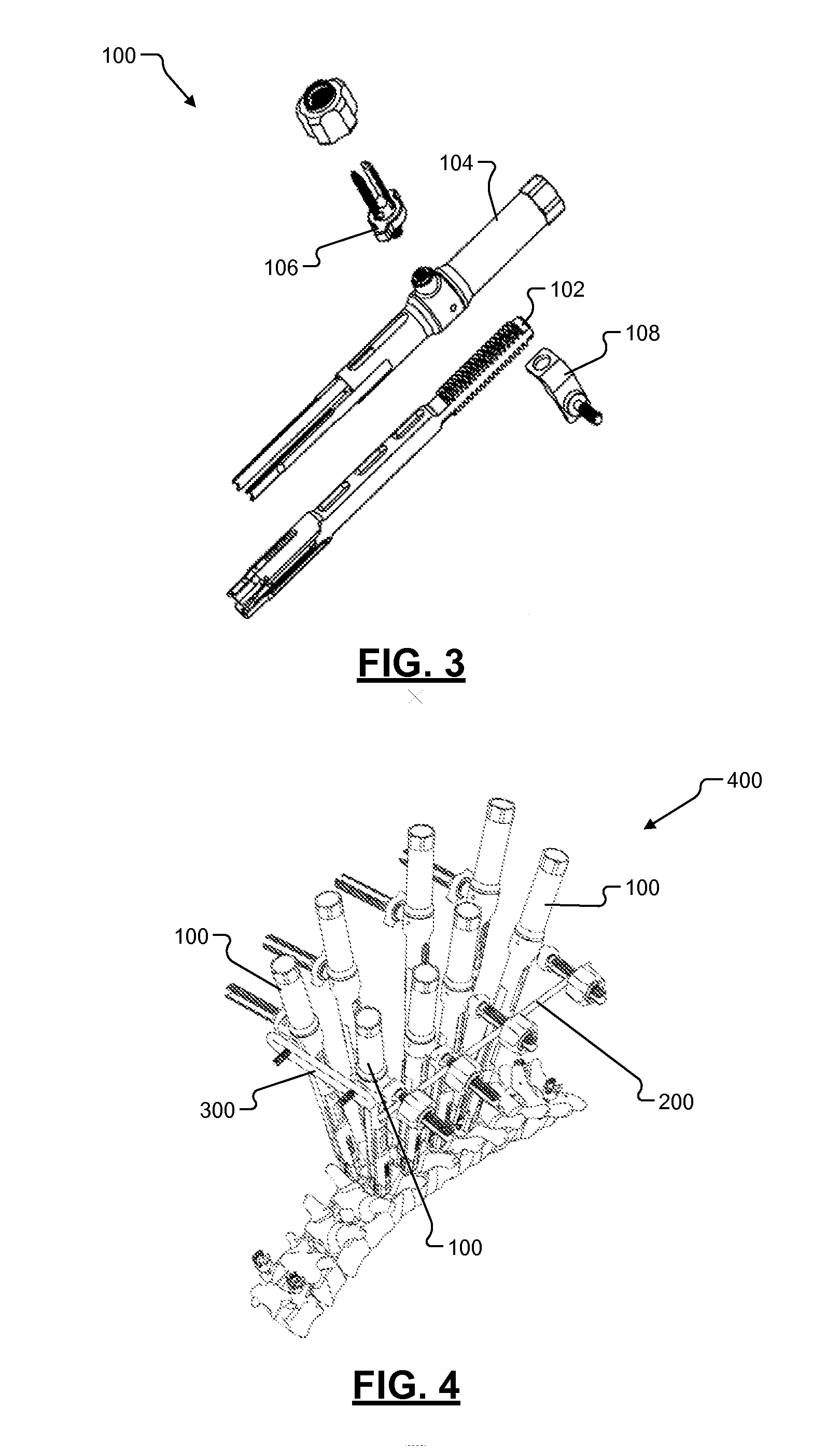
[0053]The system and method of the present invention includes various features that enable reduction of a fixation rod to an implant head, segmental vertebral body alignment, en bloc simultaneous derotation of multiple levels of vertebral bodies, and stabilization of corrected alignment while setscrews are tightened. The system reduces the complexity of spinal deformity correction procedures and decreases the risk of damage to implants and the vertebral bodies due to high stress concentration at the implant-vertebra interface.

[0054]The system comprises a first set of derotation tubes which attaches to the spinal implant heads. A second set of reduction tubes may be inserted over the derotation tubes to reduce a fixation rod to the implant heads. Each reduction tube can accommodate at least 50 mm of reduction. After the reduction of the rod to the implant heads, setscrews may be coaxially inserted to retain the rod to the implant heads. A segmental alignment attachment may be added t...


PUM


Abstract

An instrument for correction of spinal deformities includes an inner member with a proximal portion configured to receive a corrective force and a distal coupling portion configured to transfer the corrective force to a spinal implant in a vertebra. A slot extends transversely through the coupling portion and is configured to guide a fixation rod into the spinal implant. A threaded sleeve includes an external thread and a thru-bore that slides relative to the proximal portion. An outer member couples with the proximal portion and threadably engages the external thread to apply a reduction force as the outer member rotates relative to the inner member. A reduction blade includes a proximal interlocking portion that removably couples with the threaded sleeve and a distal rod engagement feature configured to engage the fixation rod and transfer the reduction force to reduce the fixation rod into the spinal implant.

Description

CROSS-REFERENCE TO RELATED APPLICATIONS[0001]The present application claims priority to U.S. Provisional Application Ser. Nos. 61 / 770,897 which was filed on Feb. 28, 2013 and 61 / 799,009 which was filed on Mar. 15, 2013, both entitled “Spinal Derotation Systems and Methods” and incorporated herein by reference in their entireties.FIELD[0002]The invention generally relates to spinal surgery and more particularly to instruments and methods for correcting spinal deformities and reducing spinal rods.BACKGROUND[0003]The spine is a flexible column formed of a plurality of bones called vertebrae. The vertebrae are hollow and piled one upon the other, forming a strong hollow column for support of the cranium and trunk. The hollow core of the spine houses and protects the nerves of the spinal cord. The different vertebrae are connected to one another by means of articular processes and intervertebral, fibrocartilaginous bodies. Various spinal disorders may cause the spine to become misaligned...

Claims


Application Information

Patent Timeline
IPC IPC(8): A61B17/70
CPCA61B17/7083A61B17/7079A61B17/708A61B17/7085A61B17/7086
Inventor PARIKH, ANANDGLEESON, GARRETTWALTERS, CARMENTIMM, JENS PETERCOSTABILE, JONATHANGILLESPIE, WALLYHUTTON, CLARK
Owner ALPHATEC SPINE INC
Why Eureka
Try Eureka