Methods for designing an exhaust assembly for a vehicle

a technology for exhaust assemblies and vehicles, applied in the direction of machines/engines, mechanical equipment, instruments, etc., can solve the problems of adverse impact on these decorative features, customer dissatisfaction is one adverse impact associated, and the gtdi engine of gasoline turbocharged is particularly prone to this problem

Inactive Publication Date: 2014-10-23
FORD GLOBAL TECH LLC
View PDF6 Cites 10 Cited by
  • Summary
  • Abstract
  • Description
  • Claims
  • Application Information

AI Technical Summary

Problems solved by technology

The exhaust soot and/or condensate often deposits, discolors and otherwise adversely impacts these decorative features.
Customer dissatisfaction is one adverse impact associated with these effects.
Vehicles with gasoline turbocharged direct injection (GTDI) engines are particularly prone to this problem.
These engines produce high levels of carbon soot due to the level of e

Method used


Image

  • Methods for designing an exhaust assembly for a vehicle
  • Methods for designing an exhaust assembly for a vehicle
  • Methods for designing an exhaust assembly for a vehicle

Examples


Embodiment Construction

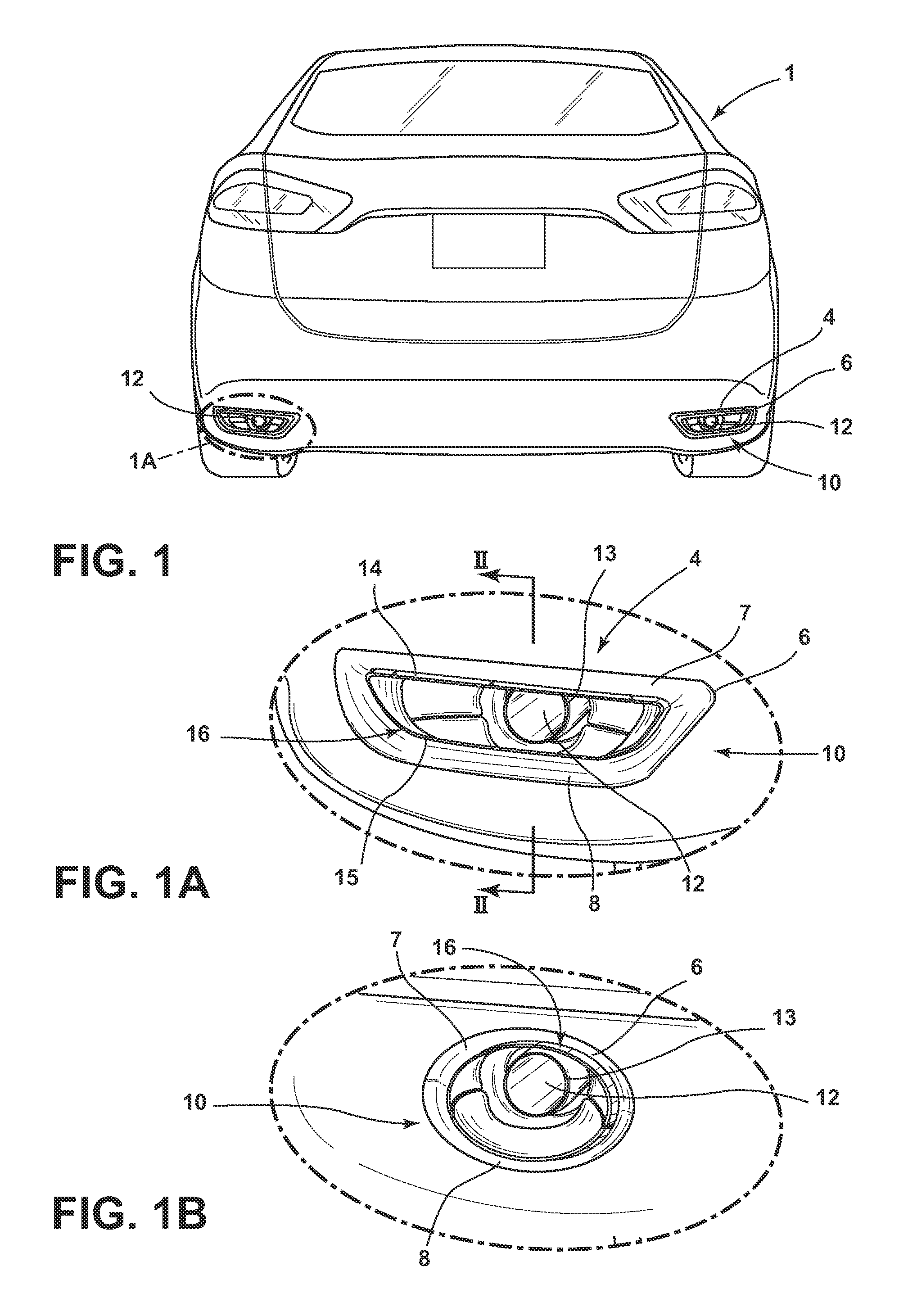
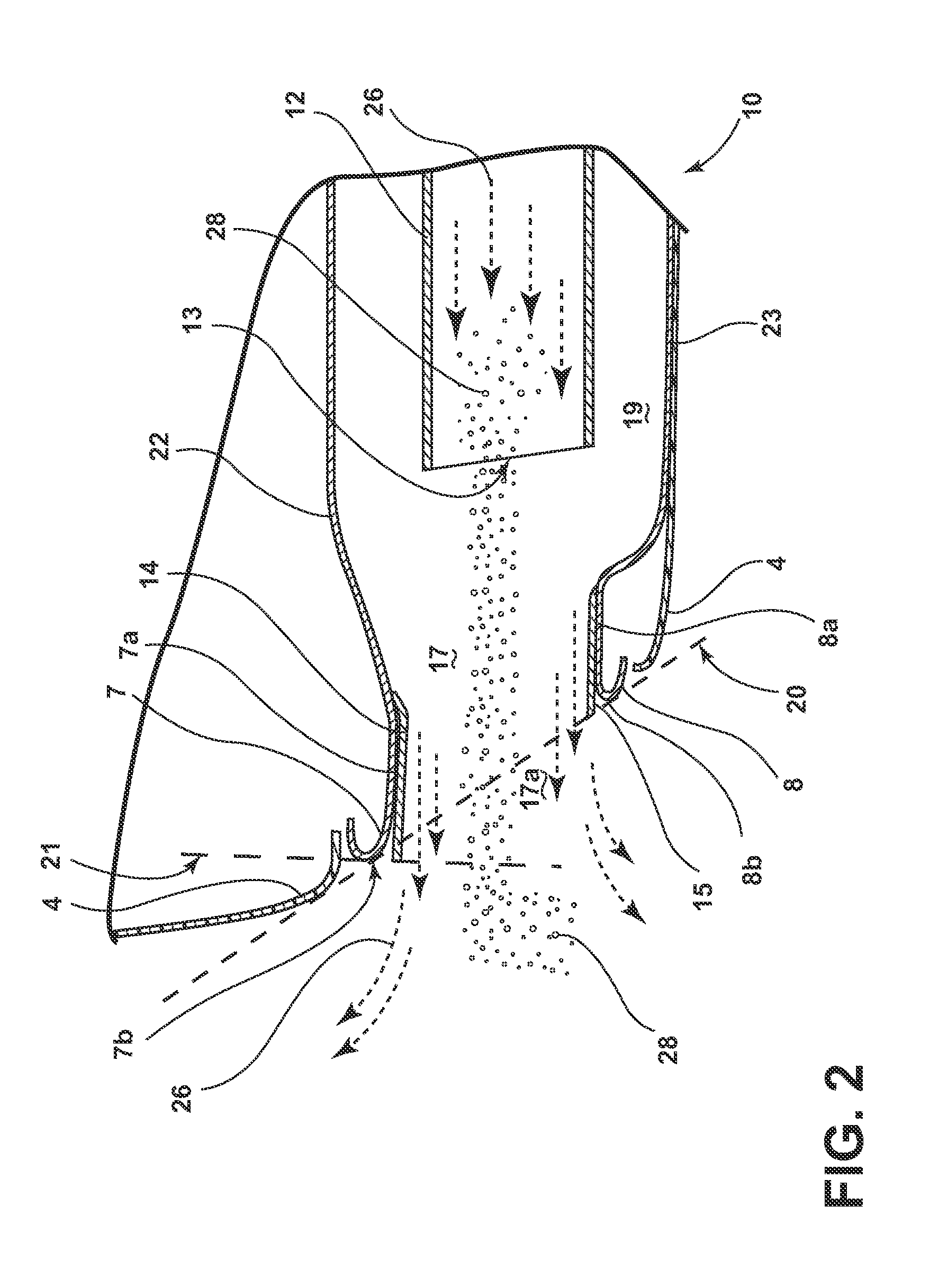
[0038]For purposes of description herein, the terms “upper,”“lower,”“right,”“left,”“rear,”“front,”“vertical,”“horizontal,” and derivatives thereof shall relate to the invention as oriented in FIGS. 1, 1A, 7, 11B and 12C. Further, the terms “forward,” and “rearward,” shall relate to the invention as oriented in FIGS. 2-6, 7A, 11A, 11C, 12A and 12B relative to the forward and rearward directions associated with a vehicle, respectively. However, the invention may assume various alternative orientations, except where expressly specified to the contrary. Also, the specific devices illustrated in the attached drawings and described in the following specification are simply exemplary embodiments of the inventive concepts defined in the appended claims. Hence, specific dimensions and other physical characteristics relating to the embodiments disclosed herein are not to be considered as limiting, unless the claims expressly state otherwise.

[0039]Various exhaust assemblies are employed today ...


PUM


Abstract

A method of designing an exhaust assembly that includes the steps: developing an initial exhaust assembly design; evaluating the initial design based on a design guide; developing an interim exhaust assembly design, or a plurality of interim exhaust assembly designs, based on the initial design and a parametric model; evaluating the interim design or designs using a computational fluid dynamics model; and developing a final exhaust assembly design based on the parametric and the fluid dynamics models.

Description

CROSS-REFERENCE TO RELATED APPLICATION[0001]This application is a continuation-in-part of U.S. patent application Ser. No. 13 / 865,459, filed on Apr. 18, 2013, entitled “PROTECTIVE SHIELD TO REDUCE EXHAUST SOOT AND CONDENSATE DEPOSITION.” The aforementioned related application is hereby incorporated by reference.FIELD OF THE INVENTION[0002]The present invention generally relates to exhaust assemblies for vehicular applications and, more particularly, to exhaust assemblies suitable for use in through-fascia, decorative exhaust tip and other vehicular exhaust system designs, along with methods of designing them.BACKGROUND OF THE INVENTION[0003]Many vehicles currently employ exhaust systems with decorative features in close proximity to the tailpipe and related components. Often these decorative features are curved and in close proximity to exhaust soot and condensate emanating from the tailpipe of vehicles during operation. The exhaust soot and / or condensate often deposits, discolors a...

Claims


Application Information

Patent Timeline
IPC IPC(8): G06F17/50
CPCG06F17/5095F01N13/082F01N13/20G06F30/15
Inventor ZHANG, YAHONGWETZEL, CRAIG RICHARDHOWE, JEREMY
Owner FORD GLOBAL TECH LLC
Why Eureka
Try Eureka