However, these tubes can be easily expanded, stretched and deformed under
high pressure to reduce their sealing effect, and while delivering high-temperature fluids, the strength of pipe joints may also be reduced so as to lower the sealing effect.
Such aforesaid situations may generate minute leakage.
Meanwhile, large leakage on pipe joints may be caused by water hammering effect or unexpected external stretch on
piping during the delivery process.
In addition, leakage can also occur due to excessive compression or pressing on the tube wall of pipe joints, resulting in tube
wall material fatigue, reduced compression ability and breakage caused by damages.
In addition, when the tubes are used long-term under consistent external force,
high pressure and other conditions, their wall materials will simultaneously subjected to
etching corrosion, infiltration and degradation.
Coupled with an increase in seal leakage on the original sealed surface, there is a possibility to cause rapid
fluid leakage phenomenon on nearby walls that cannot be detected with the
naked eye.
Based on these physical properties and application requirements, the following precautions are needed while designing pipe joints of PFA tubes:(1) The
smooth surface and low
frictional coefficient of sliding of PFA is a characteristic to generate poor surface adhesion, and made it unsuitable to use on pressurized surface sealing.
However, it is still not recommended to exert with excessive compression force F to cause
wall material fatigue, resulting in inability to withstand the requirement of 20
assembly / disassembly cycles without leaking.(2) High elongation represents that the
wall material can be easily subjected to move and cause the wall thickness to thin down due to elongation in the event of pressure or stretch.
This will cause a decrease in compression volume of tube wall following the movement of material, resulting in reduced or invalid sealing effect, as well as easy slipping off of tubes when subjected to external stretch.(3) The material strength will decrease following an increase in temperature, i.e. a
strength reduction for all pipe joint components that subjected to compression force and a possible leak caused by a drop in compression force on the compressed tube wall.(4) While installing a pipe joint, a jig is often used to perform heated or unheated flaring operation.
This will relatively lower the effectiveness in performing compressive sealing on tube wall thickness.
When the pipe joint is fastened, the compression ring on fixed ring will not be able to force the cone tube to abut the
conical surface to form a sealed surface as it is non-annular.
An even compression deformation can only be generated when the sealed surface is in annular or near annular shape, but these compression deformations will lost part of the elasticity due to prolonged
creep, or a reduction in compression force.
Besides reducing the strength while performing high-temperature
leakage test or delivering high-temperature fluid, it will also accelerate the occurrence of
creep.
This will also accelerate the
creep phenomenon to lower the compression force and increase the risk of high sealing leakage.
To achieve the sealing effect through increasing the high
axial compression volume exceeding the reasonable limits is not a solution, as an excessive compression volume will accelerate the sealed surface's wall fatigue and deformation and reduce its ability to withstand the requirement of 20
assembly / disassemble cycles without leaking, or a decrease in
pressure resistance ability during the high-temperature
leakage test.(13) Sliding friction: although PFA surface has a self-
lubrication characteristic, but a relative sliding friction between the sealed surface's compression ring and the tube wall may be generated during the fastening process.
If there is a defect in sealed surface's tube wall, compression ring and conical surface, it may cause damages to the tube wall.(14) Frictional risks: there is an occurrence of sliding friction during the entire fastening process of twisting the circumferential angle, causing a higher frictional risk of tube wall damages.
The smaller the circumferential twisting angle, the lower is the frictional risk of sliding friction.
Coupled with an adverse deformation of compression ring, there is a highest possibility of frictional risk on tube wall.
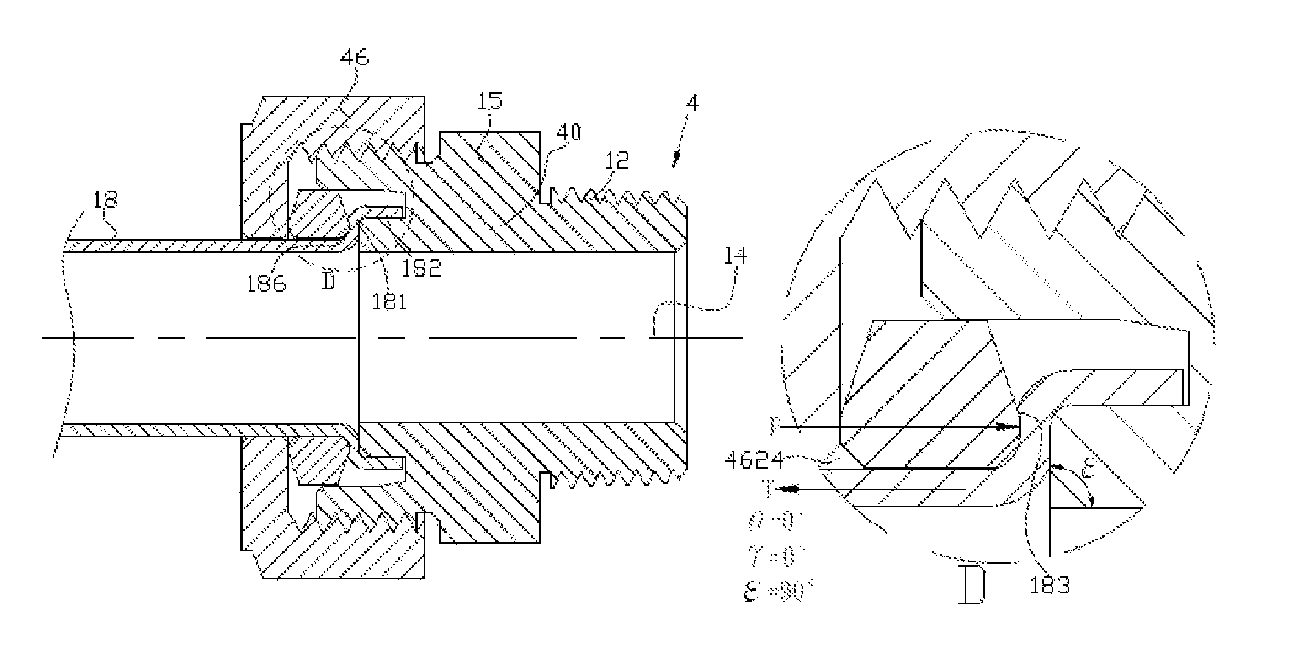
There is an existence of high frictional risk of sliding on the sealed surface (183) throughout the entire locking process.
However, as the angle of applied included angle θ is closed to 45°, it will cause Fn distribution force to fall and prevent the pulling resistance ability to improve further.
This has however, enlarged the outside
diameter at the same time and needed a larger installation space.
So, such structure has still possessed a high frictional risk.
Such structure is unable to improve the pulling resistance ability.
In addition, as it is unsure to maintain the disc-shaped anchor plate (77) at its center position during the locking process, it is thus unable to guarantee that the applied force angle γ of compression force F will cause an uneven non-annular or elliptical force distribution to reduce the sealing effect and pulling resistance ability.
If softer PFA material is used in disc-shaped anchor plate (77), its compression ring (7721) will be restricted by the compression angle γ of near 0°, causing unfavorable stress deformation, and Fn distribution force will drop even lower and unable to meet with tensile test and high temperature test.
This will still increase the leakage risk problem.
This is particularly obvious under high temperature as its compression strength will drop and not beneficial to use tube wall thickness in compression sealing.
The complex
coupling structural strength of third sealing section is relatively weak as it tends to deform under high temperature and during the compression process.
This can easily damage the embedded fixed ring (87) and has to replace the entire fixed ring (87) and joint body (80), causing inability to reuse the pipe joint (8), and increase maintenance time and material costs.
The reason of high frictional risk is caused by sliding friction on the sealed surface during the locking process.
Although the sealed surface (194) has been hardened by the jig, but there is an existence of direct sliding friction throughout the entire locking process to generate a very high frictional risk.
Although there has been a slight improvement in the sealing effect and pulling resistance ability, but it still faces the entire structural complexity issue for being easily deformed and a possibility to replace the embedded fixed ring (87) and pipe joint (80), etc.
Furthermore, a need to use a special jig will also increase the construction and maintenance burden and costs.
As the sliding friction will occur throughout the entire locking process, it is unable to lower the risk of tube wall damages, including a possibility for being unable to meet the requirement of withstanding 20
assembly / disassembly cycles without leaking.
This compression angle cannot be smaller than 60° as too small of it will damage the tube wall.
If no disc-shaped anchor plate is used, this structural compression force will be high but the pulling resistance will be low.
In addition, as it is hard to ensure that the disc-shaped anchor plate will maintain at its central position during the locking process, it is thus unable to guarantee that the applied force angle γ of compression force F will generate an uneven non-annular or elliptical uneven force distribution to reduce the sealing effect and pulling resistance ability.
In addition, as the disc-shaped anchor plate is pressed against the tapered opening's inner side of union nut, it may rotate to generate a sliding friction on the second sealed surface during the locking process, and so unable to lower the frictional risk of tube wall damages.
So it is unable to further enhance the pulling resistance ability and also unfavorable for the tube wall to generate a continuous annular cumulative deformation.
This will cause a sliding friction on the sealed surface (183) and will still generate a high frictional risk.
When dual-cone fixed ring (17) is replaced with a softer PFA material, its compression ring (1701) will demonstrate an even greater deformation, causing Fn distribution force to fall even lower and result in poorer sealing ability.

