

Dynamic power flow controllers
a technology of dynamic power flow and controller, which is applied in the direction of electric variable regulation, process and machine control, instruments, etc., can solve the problems of limiting the capacity affecting the reliability of the electric power system, and extreme complexity, so as to reduce the cost and complexity of such implementations, and eliminate the need for complex platforms
- Summary
- Abstract
- Description
- Claims
- Application Information
AI Technical Summary
Benefits of technology
Problems solved by technology
Method used
Image


Examples
Embodiment Construction
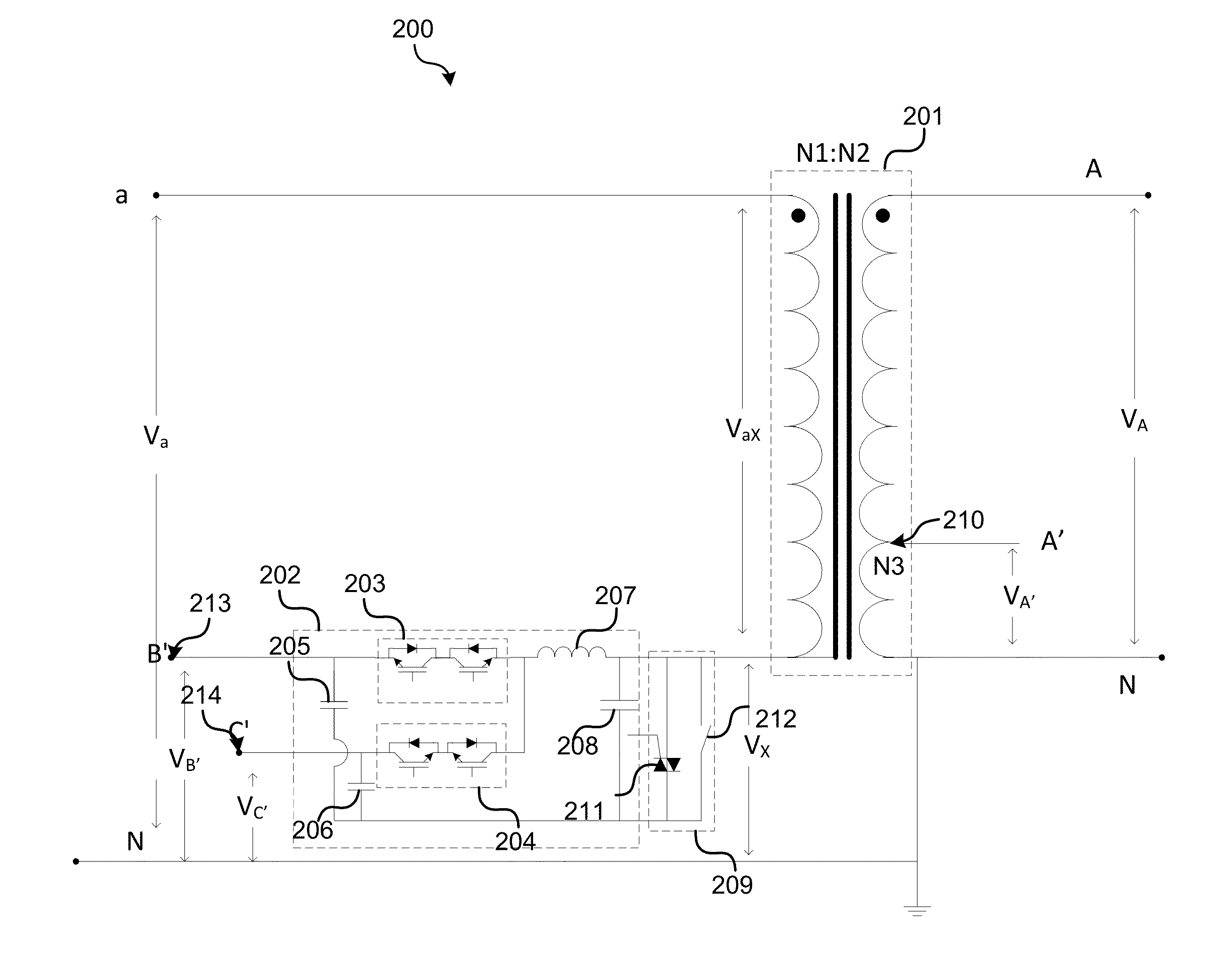
[0006]Methods and systems of dynamic power flow controllers are provided. Various embodiments may comprise a transformer and a power converter. The power converter is subject to low voltage stresses and not floated at line voltage. In addition, the power converter is rated at a fraction of the total power controlled. The power converter operates at close to neutral and ground potential, which may eliminate a need for complex platforms as well as isolation techniques. As such, the cost and complexity of such implementations may be reduced significantly.
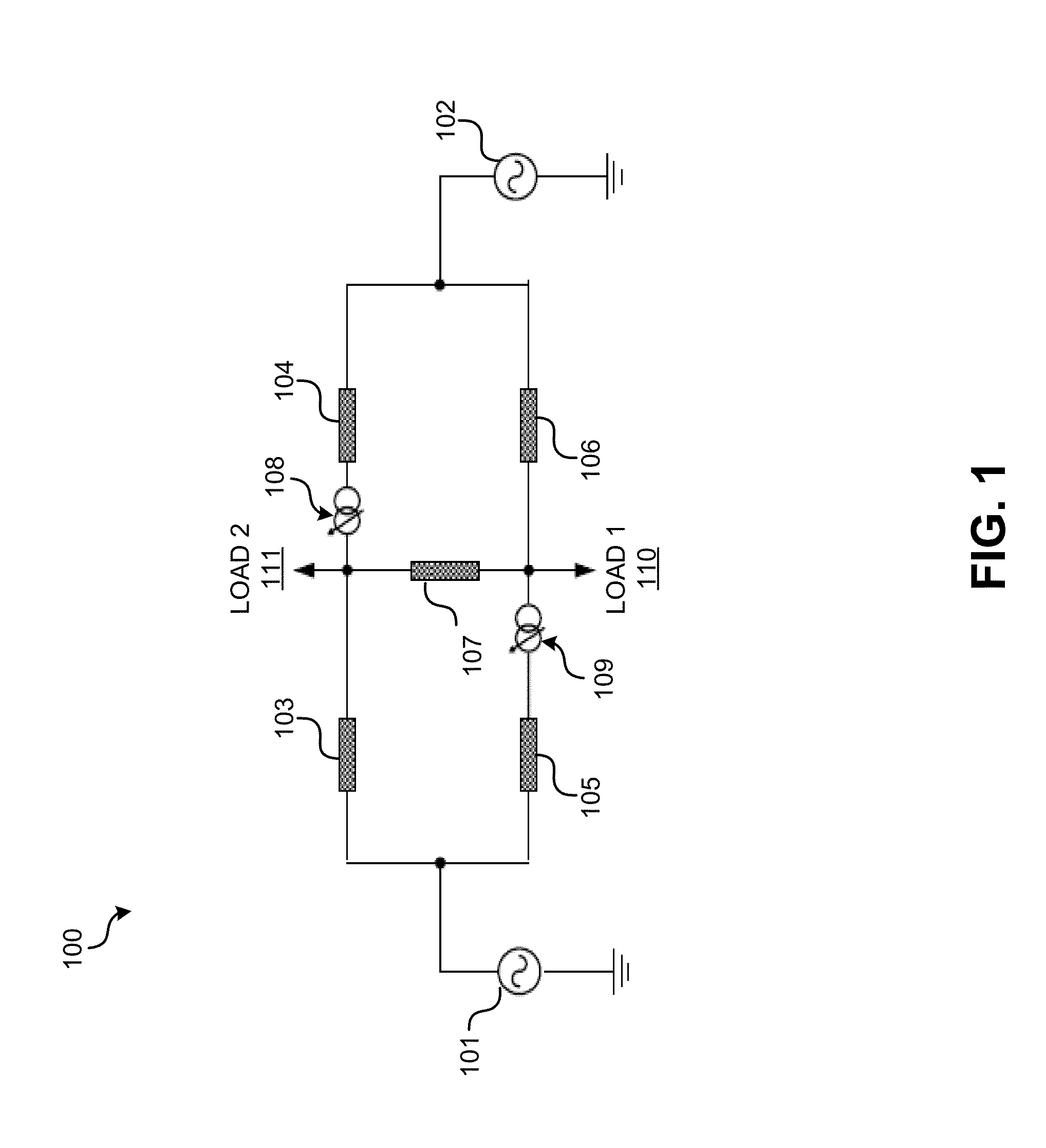
[0007]Dynamic power flow controllers may be implemented in a single-phase or in a three-phase configuration, but the operation of a dynamic power flow controller cross-couples all three phases. A dynamic power flow controller may be installed around a sectionalizer device at a T-junction such that dynamic power flow controllers may be deployed into a meshed grid. Further, various embodiments may act autonomously but in a coordinated ma...
PUM
 Abstract
Description
Claims
Application Information