Device and method for dazzle protection

a technology of dazzle protection and device, applied in the field of dazzle protection or glare protection, can solve the problems of unsatisfactory anti-glare performance of darkening welding filters, insufficient efficiency, and disturbing low frequency pulsing and glaring perception of welds, so as to avoid or minimize the disturbance of welders

Inactive Publication Date: 2014-10-30
OPTREL AG
View PDF0 Cites 16 Cited by
  • Summary
  • Abstract
  • Description
  • Claims
  • Application Information

AI Technical Summary

Benefits of technology

[0009]It is therefore an object of the invention to create an auto-darkening welding filter and a method for operating an auto-darkening welding filter for protecting a welder's eye in the course of a pulse mode welding process, which overcomes the disadvantages mentioned above and provides an improved solution to avoid or minimize disturbance of the welder by low frequency pulsing light flashes.

Problems solved by technology

State-of-the-art anti-glare protection helmets or auto-darkening welding filters (ADF) show an unsatisfactory anti-glare performance, since a pulsing welding arc is perceived, although the ADF operates in the respective protective mode.
The combined delay of the opto-electronic system of these products produces an extremely disturbing, low frequency pulsing and glaring perception of the weld.
Recent attempts to solve the problem (e.g. fixed scale number, or automatic adjustment of the shade between two pre-set scale numbers; e.g. U.S. Pat. No. 8,331,001) are either not efficient enough.
They use a fixed scale number or amplify the effect due to trigger delays and they have a long decay time of the LCD shutter and a slow reaction time of the transmission control circuit (two-scale number automatic adjustment).
That means that the welder is extremely disturbed by the low frequency flashing nature of the pulse mode welding process.
The flashing nature of modern pulsing arc sources is responsible for the continuous overload of the visual system of the welder which is the reason that welding personnel are increasingly suffering under the disturbing and tiring effects of pulsed arc welding sources.
Current anti-glaring protection helmets are not fast enough to follow the steep, high amperage pulse train due to the combined electronic delays of the transmission control circuit.
Therefore, a short flash reaches the eye and the neurological system, triggers the discomfort.
These modes incorporate the important gray scale capability but produce asymmetrical switching times due to the self-relaxing decay time.
The self-relaxing turn-off time does, on the other hand, not allow to follow the fast decay time of a pulsed welding arc source.
This means that the liquid crystal shutter is not able to adapt from a high scale number needed in the course of high amperage pulses to a much lower scale number of the melt-off current in time.
The welding community does not accept such concepts as the welder does not want to have wire connections to the equipment and / or he wants to have the freedom to choose a specific welding protection helmet that is independent from the equipment.

Method used


Image

  • Device and method for dazzle protection
  • Device and method for dazzle protection
  • Device and method for dazzle protection

Examples


Embodiment Construction

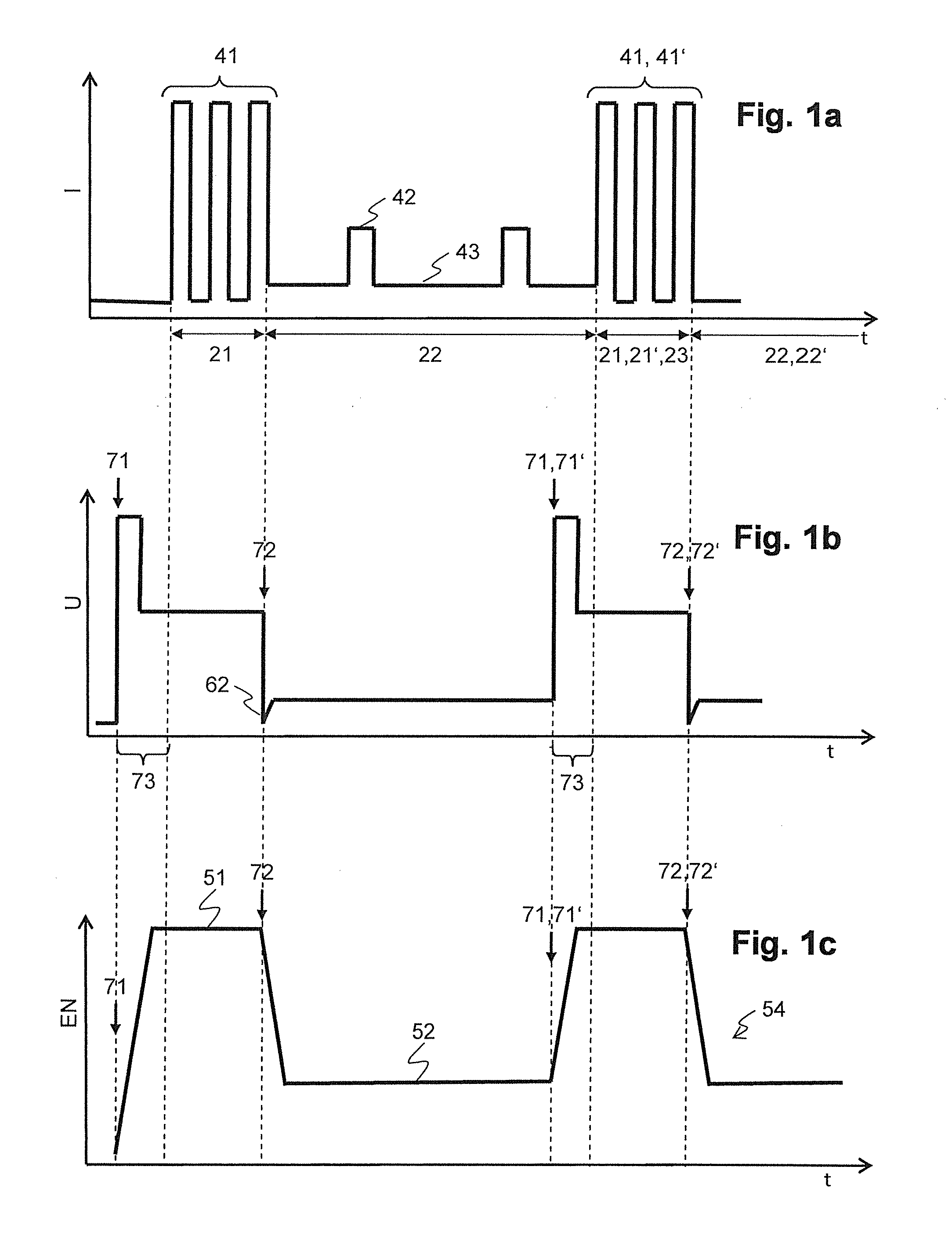
[0039]FIG. 1a schematically shows a characteristic trajectory of a welding current of a pulse mode welding process over time. During a pulse mode welding process a high amperage pulse train 41 is provided, with e.g. the current rising up to 500 A. The high amperage pulse train 41 features a very short rise times of a rising edge and very short lowering times of a falling edge of a single pulse with a repetition rate of couple of kHz, and even more particular between 0.5 to 20 kHz, in particular between 1 to 10 kHz. The high amperage pulse train 41 can have a length of for example 180 ms, an intermediate lower current pulse train can have a length of for example 20-30 ms.

[0040]The high amperage pulse train 41 quickly heats up the material. After the high amperage pulse train 41 the current is reduced (holding current 43) and is followed by a lower current pulse train (melt-off current 42). Due to the pulses with the melt-off current 42, filler material is melted, whereas during each ...


PUM

PropertyMeasurementUnit
frequencyaaaaaaaaaa
timeaaaaaaaaaa
timeaaaaaaaaaa

Abstract

A method for operating an auto-darkening welding filter for protecting a welder's eye in the course of a pulse mode welding process. During the pulse mode welding process at least a first time interval with strong light emission and a second time interval with reduced and / or negligible light emission are repeated with a repetition rate, and a point in time of a beginning of the first time interval is associated with a raising edge event. The method includes the step of darkening the auto-darkening welding filter to a first darkening level at a point in time of the raising edge event that is associated with a next first time interval.

Description

BACKGROUND OF THE INVENTION[0001]1. Field of the Invention[0002]The invention relates to the field of dazzle or glare protection. It relates to an auto-darkening welding filter and a method for operating an auto-darkening welding filter for protecting a welder's eye in the course of a pulse mode welding process.[0003]2. Description of Related Art[0004]Advanced pulsed welding methods (e.g. MIG / MAG or TIG “Tungsten Inert Gas”) use a pulse train of high current pulses, incorporating very fast rise times to quickly warm up the material. The current then is reduced to a minimum (hold current) and is followed by a lower current pulse train, which melts filler material into the liquid weld on a drop-to-drop basis. This procedure provides a very stable welding process, an improved welding efficiency under difficult welding conditions and it will allow joining different materials.[0005]The overall repetition rate of the pulsed high current phase combined with the lower hold current phase is ...

Claims


Application Information

Patent Timeline
Patent Type & Authority Applications(United States)
IPC IPC(8): A61F9/06G02F1/133
CPCA61F9/067G02F1/13306G02F1/13318
Inventor KELLER, LEOSCHREIBER, MARTINTETZEL, TOBIAS
Owner OPTREL AG
Why Eureka
Try Eureka