Laser Machining Head with Integrated Sensor Device for Focus Position Monitoring

a laser processing head and sensor technology, applied in laser beam welding apparatus, instruments, optics, etc., can solve the problems of uncontrollable change of focus position, temperature gradient formation, and increase of optical stress on laser processing head optical components in a previously unknown manner

Inactive Publication Date: 2010-11-04
JENOPTIK AUTOMATISIERUNGSTECHN
View PDF4 Cites 23 Cited by
  • Summary
  • Abstract
  • Description
  • Claims
  • Application Information

AI Technical Summary

Benefits of technology

[0027]It is the problem of the invention to find a laser machining head with an integrated sensor device with which an uncontrolled change of focus position can be precisely detected, in order to compensate for this exceeding of the specified tolerance limit in a regulated manner.

Problems solved by technology

In particular, when solid-state lasers with high power and beam quality, such as multi-kilowatt fiber lasers, are used, thermal stress on the optical components of the laser processing head increases in a previously unknown manner.
Since the laser beam does not completely illuminate the entire surface of an optical element, and the intensity distribution is not uniform over the beam cross section, the formation of a temperature gradient occurs in addition to the actual heating.
In both cases, an uncontrolled change of focus position is undesired.
It can lead to a considerable reduction in the quality of the process result.
In the extreme case, the machining process is no longer possible.
As is presented in detail, these control signals are influenced by a number of process parameters, and are therefore less suitable.

Method used


Image

  • Laser Machining Head with Integrated Sensor Device for Focus Position Monitoring
  • Laser Machining Head with Integrated Sensor Device for Focus Position Monitoring

Examples


Embodiment Construction

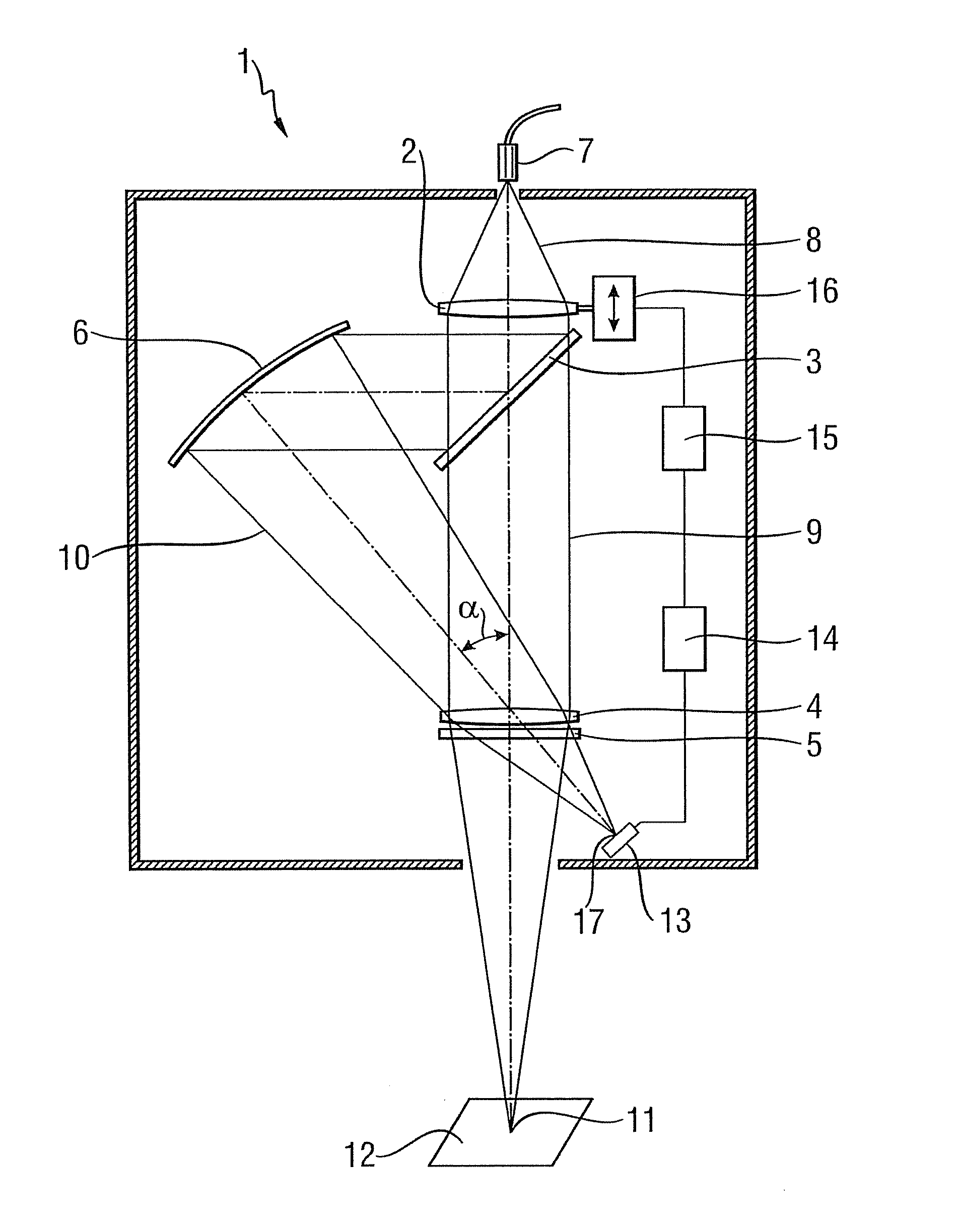
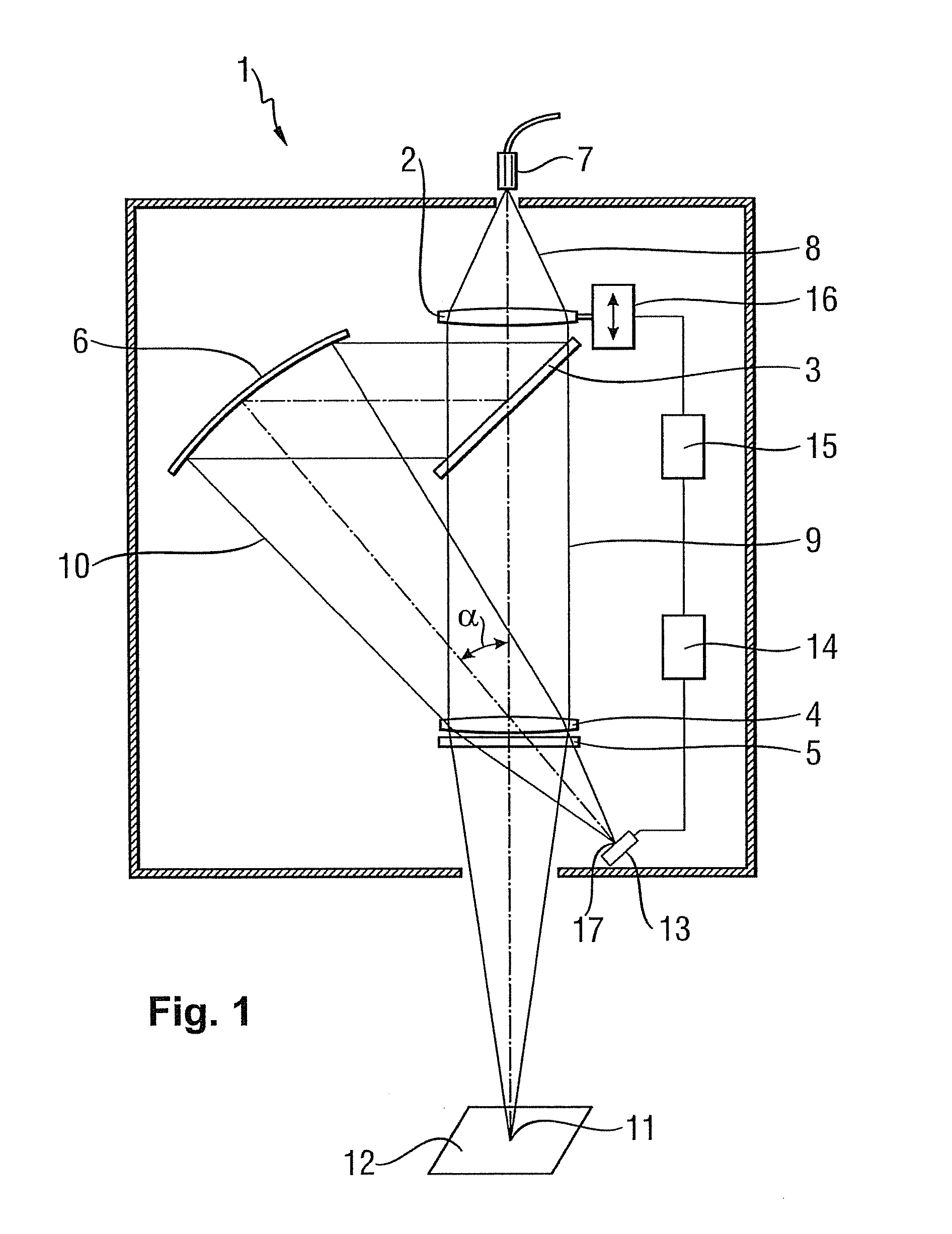
[0037]The advantageous embodiment of the laser machining head 1 shown in FIG. 1 has a collimating lens 2, a beam splitter 3, a focusing lens 4, a downstream protective glass 5 and a mirror 6 as its optical elements.

[0038]A laser beam 8 is coupled into laser machining head 1 in the direction of the optical axis of collimating lens 2 via a beam entry opening at which the exit face of an optical fiber 7 is arranged and which is situated in the focal plane of collimating lens 2. The laser beam 8 parallelized by collimating lens 2 strikes beam splitter 3, which divides laser beam 8 into a machining beam 9 and a measurement beam 10. Beam splitter 3 can be a geometrically splitting as well as a physically splitting beam splitter 3. Beam splitter (3) is transmissive for a first portion of a laser beam (8) coupled into laser machining head (1) and is reflective for a second portion. The first portion of the laser beam is the machining beam (9), and the second portion is the measuring beam (1...


PUM

PropertyMeasurementUnit
reflectivityaaaaaaaaaa
angleaaaaaaaaaa
focal lengthaaaaaaaaaa

Abstract

The invention relates to a laser machining head (1) with an integrated sensor device for monitoring the focus position, wherein laser machining head (1) has a focusing lens (4) and a downstream protective glass (5) in order to focus a machining beam (9) that strikes focusing lens (4) as a parallel beam into a resultant focal point (11) of focusing lens (4) with downstream protective glass (5), in which focal point a workpiece (12) is arranged. A beam splitter (3), arranged upstream of focusing lens (4) in the beam path, is transmissive for a first portion of a laser beam (8) coupled into laser machining head (1), the machining beam (9), and is reflective for a second portion, a measurement beam (10). In the reflection direction, a mirror (6) is arranged downstream of beam splitter (3) in such a manner that it reflects measuring beam (10) at an angle a to the optical axis of focusing lens (4) onto the latter in order to image it in an image point (17), conjugate with focal point (11), on the receiving surface of sensor (13) that is connected to an evaluation unit (14) for focus position monitoring.

Description

FIELD OF THE INVENTION[0001]The invention relates to a laser machining head of the type known from DE 10 2004 020 704 A1.BACKGROUND OF THE INVENTION[0002]In material machining processes, the quality of the process result is crucially dependent on the stability of the process parameters, which is why process parameters that can change in an uncontrolled manner during the machining process are monitored and also readjusted.[0003]A known measure in laser material machining is to monitor the fluctuations of the laser power by coupling out a certain portion of the laser beam and routing it to a radiation-sensitive sensor. The received signal can then be used to regulate the laser power.[0004]Monitoring the laser machining process by detecting radiation coming from the area of interaction between the laser beam and the workpiece is also known. For this purpose a dichroic mirror, for example, which allows the laser radiation to pass without hindrance but reflects the radiation coming from ...

Claims


Application Information

Patent Timeline
Patent Type & Authority Applications(United States)
IPC IPC(8): B23K26/00
CPCB23K26/046G02B27/16B23K26/428B23K26/422B23K26/702B23K26/707B23K26/04B23K26/064
Inventor REITEMEYER, DANIELPARTES, KNUTSEEFELD, THOMAS
Owner JENOPTIK AUTOMATISIERUNGSTECHN
Why Eureka
Try Eureka