Lamp unit

a technology for lamps and parts, applied in the field of lamps, can solve the problems of glare caused by the portion of the light, and achieve the effects of reducing assembly errors, simplifying assembly process, and reducing the number of components

a technology for lamps and parts, applied in the field of lamps, can solve the problems of glare caused by the portion of the light, and achieve the effects of reducing assembly errors, simplifying assembly process, and reducing the number of components

US20140321147A1Active Publication Date: 2014-10-30HONDA MOTOR CO LTD +1

Image

  • Lamp unit
  • Lamp unit
  • Lamp unit

Examples


Embodiment Construction

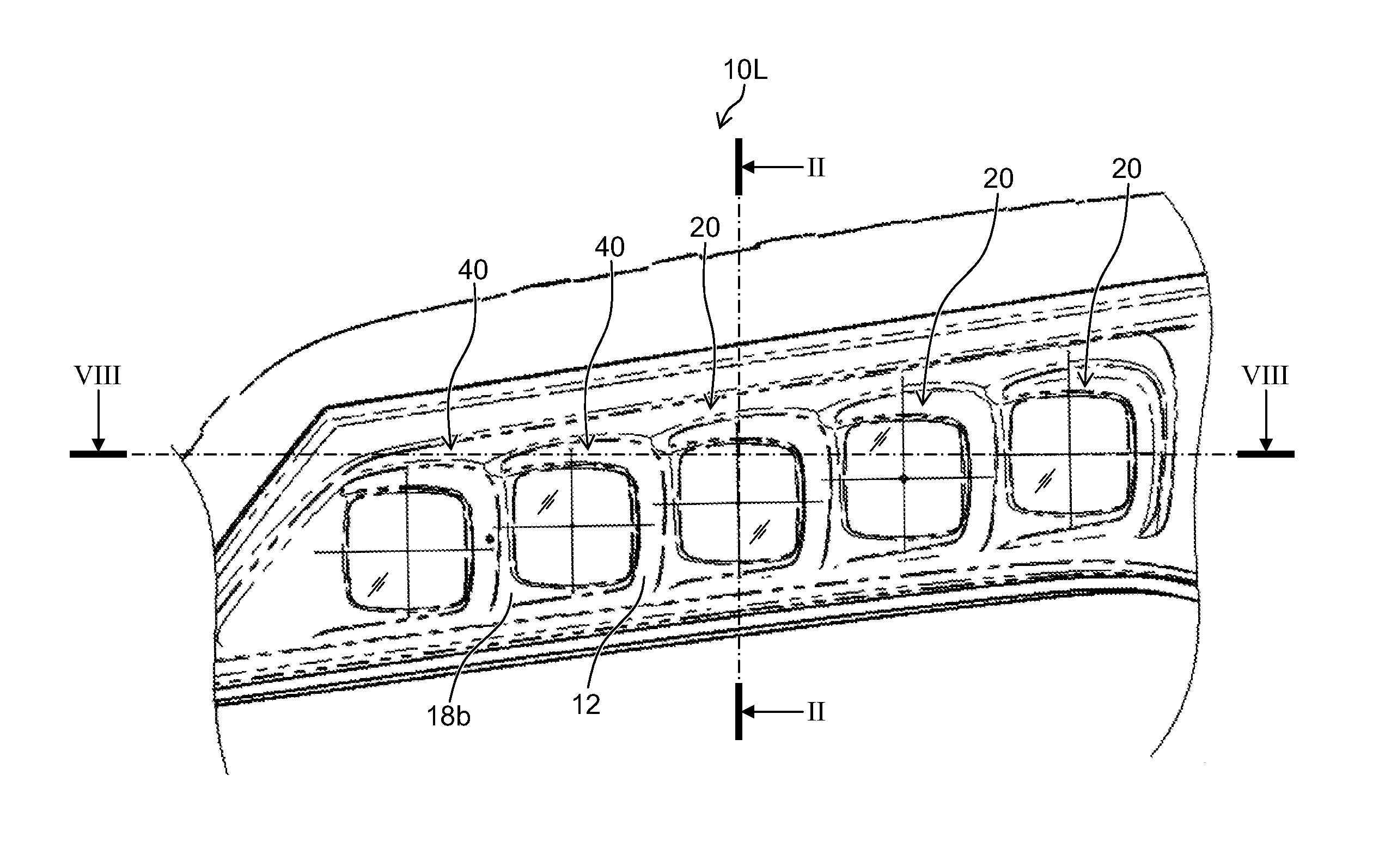
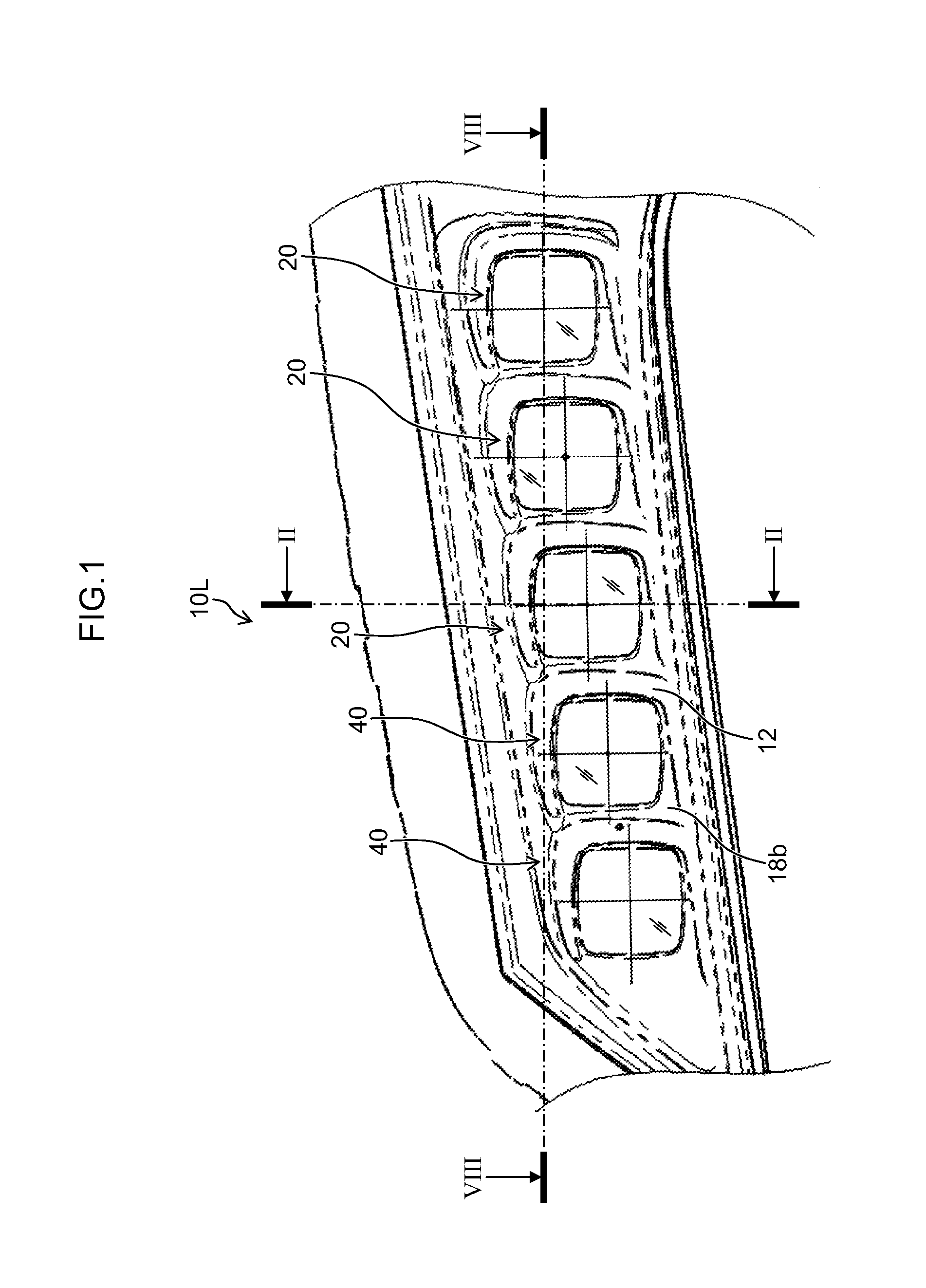
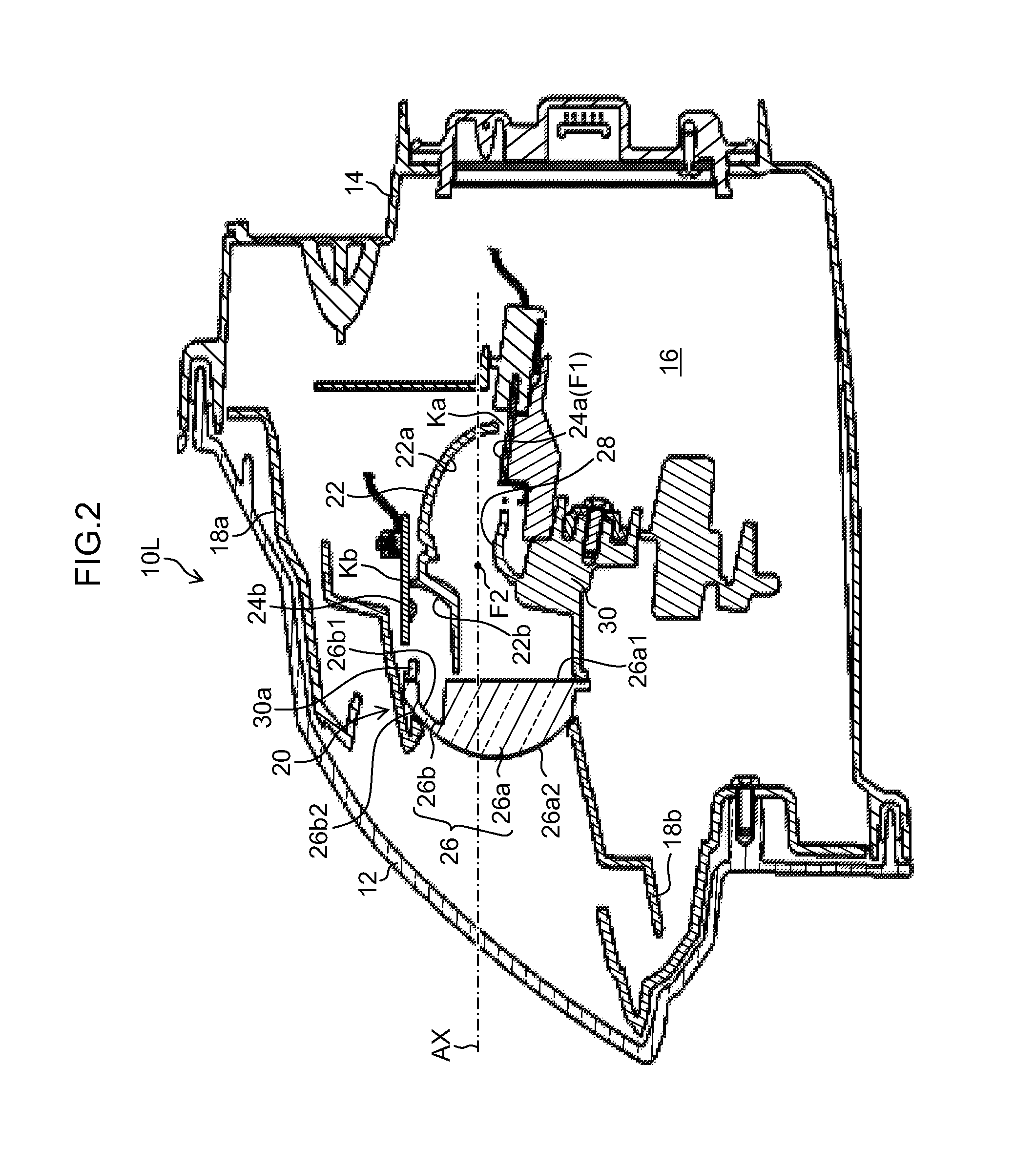
[0038]An exemplary embodiment of the presently disclosed subject matter of a lamp unit for a vehicle headlamp will be described below with reference to the drawings. FIG. 1 is a front view of a vehicle headlamp 10L disposed on a left-hand side from among vehicle headlamps disposed on a right-hand side and a left-hand side of a front portion of a vehicle such as an automobile and the like. FIG. 2 is a cross-sectional view of the vehicle headlamp 10L taken along line II-II in FIG. 1.

[0039]The vehicle headlamp 10L disposed on the left-hand side and the vehicle headlamp 10R disposed on the right-hand side can be laterally symmetrical with each other and configured substantially identical to each other. Therefore, the below description will center on the vehicle headlamp 10L disposed on the left-hand side, and a description of the vehicle headlamp 10R configured on the right-hand side will be omitted.

[0040]As illustrated in FIG. 1, the vehicle headlamp 10L can include three combined pass...


PUM


Abstract

A lamp unit for a vehicle lamp can include: a lens having an aspherical shape, including a first lens portion, and a second lens portion disposed adjacent to the first lens portion and forming a concave portion on at least a part of a rear side surface thereof; a first reflective surface disposed rearward of the first lens portion; a second reflective surface disposed rearward of the second lens portion; a first light source configured to emit light to be reflected by the first reflective surface, pass through the first lens portion and be emitted forward; and a second light source configured to emit light to be reflected by the second reflective surface, pass through the second lens portion and be emitted forward. A shape of a rear side surface of the second lens portion can be configured to diffuse the light from the second light source vertically and horizontally.

Description

CROSS-REFERENCE TO RELATED APPLICATIONS[0001]This application claims the priority benefit under 35 U.S.C. §119 of Japanese Patent Application No. 2013-092233 filed on Apr. 25, 2013, which is hereby incorporated in its entirety by reference.BACKGROUNDDescription of the Related Art[0002]Conventionally, in the field of lamps, specifically vehicle headlamps (HL), a lamp has been proposed having a configuration that incorporates, in a single unit, an optical system configuring a daytime running lamp (DRL) used for informing someone ahead of the existence of a vehicle during daytime operation, and an optical system configuring such a headlamp.SUMMARY[0003]The presently disclosed subject matter is designed in view of the above described characteristics and circumstances, and according to one aspect includes a lamp unit for a vehicle lamp with a configuration that incorporates a first light source used for a first lamp function (for example a headlamp) and a second light source used for a s...

Claims


Application Information

Patent Timeline
30 Oct 2014
Publication
US20140321147A1
IPC
F21V13/04; F21S8/10
CPC
F21S48/12; F21V13/04; F21S41/19; F21S41/295; F21S41/255; F21S41/265; F21S41/39; F21S41/336
Inventors
TODAKA, SHINICHI; FISHER, NATHAN MARION