Double shaft reactor/mixer and system including an end cap for a reactor/mixer and a discharge screw connector block

a technology of reactor/mixer and connector block, which is applied in the direction of mixers, rotary stirring mixers, transportation and packaging, etc., can solve the problems of expensive forgings, insufficient cleaning of the inner wall of the housing, etc., and achieve the effect of avoiding condensation and efficient modular assembly of these components

Active Publication Date: 2014-10-30
BUSS SMS CANZLER
View PDF7 Cites 1 Cited by
  • Summary
  • Abstract
  • Description
  • Claims
  • Application Information

AI Technical Summary

Benefits of technology

[0020]In a further preferred embodiment of the inventive reactor / mixer, the reactor / mixer comprises a large volume vapor collection space above the at least partly open housing. Such a construction may in particular serve for providing a deep pressure or a high vacuum at the product surface. Further preferred, there is arranged a baffle in the large volume vapor collection space. The baffle shall direct the resulting vapor in the direction of the vapor outlet. Further, the baffle shall avoid the formation of depositions in the lower area of the vapor collection space, which adjoins the reactor wall. Preferably, the vapor collection space housing, inclusive connector flange and vapor outlet is heatable in order to avoid condensation.
[0021]In a preferred embodiment of the inventive system, a drive for the one or the multiple discharge screws may be arranged in a detachable manner at the discharge screw connector block. For this purpose, the discharge screw connector block regularly comprises a connector flange with multiple circumferential bores, at which the drive, respectively the motor for the at least one discharge screw may be screwed on. In this way, a particularly efficient modular assembly of these components is provided.

Problems solved by technology

In particular, the inner wall of the housing is not fully cleaned kinematicallly through the gap, which is formed by the scrapers being mounted on the discs in axial direction.
The integration of the discharge screw apparatus into the end cap does however lead to expensive forgings, respectively to weldments which are expensive in production.

Method used


Image

  • Double shaft reactor/mixer and system including an end cap for a reactor/mixer and a discharge screw connector block
  • Double shaft reactor/mixer and system including an end cap for a reactor/mixer and a discharge screw connector block
  • Double shaft reactor/mixer and system including an end cap for a reactor/mixer and a discharge screw connector block

Examples


Embodiment Construction

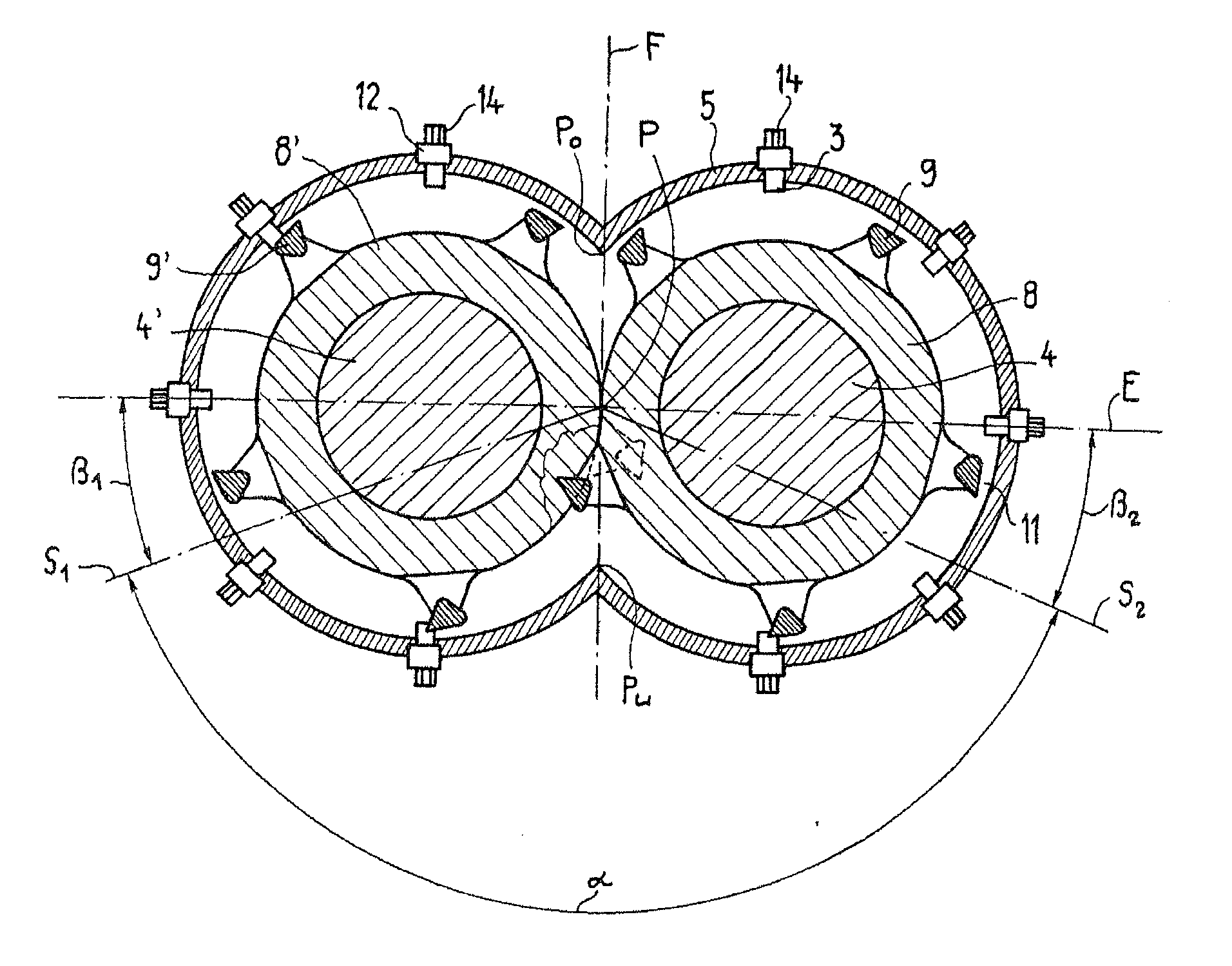
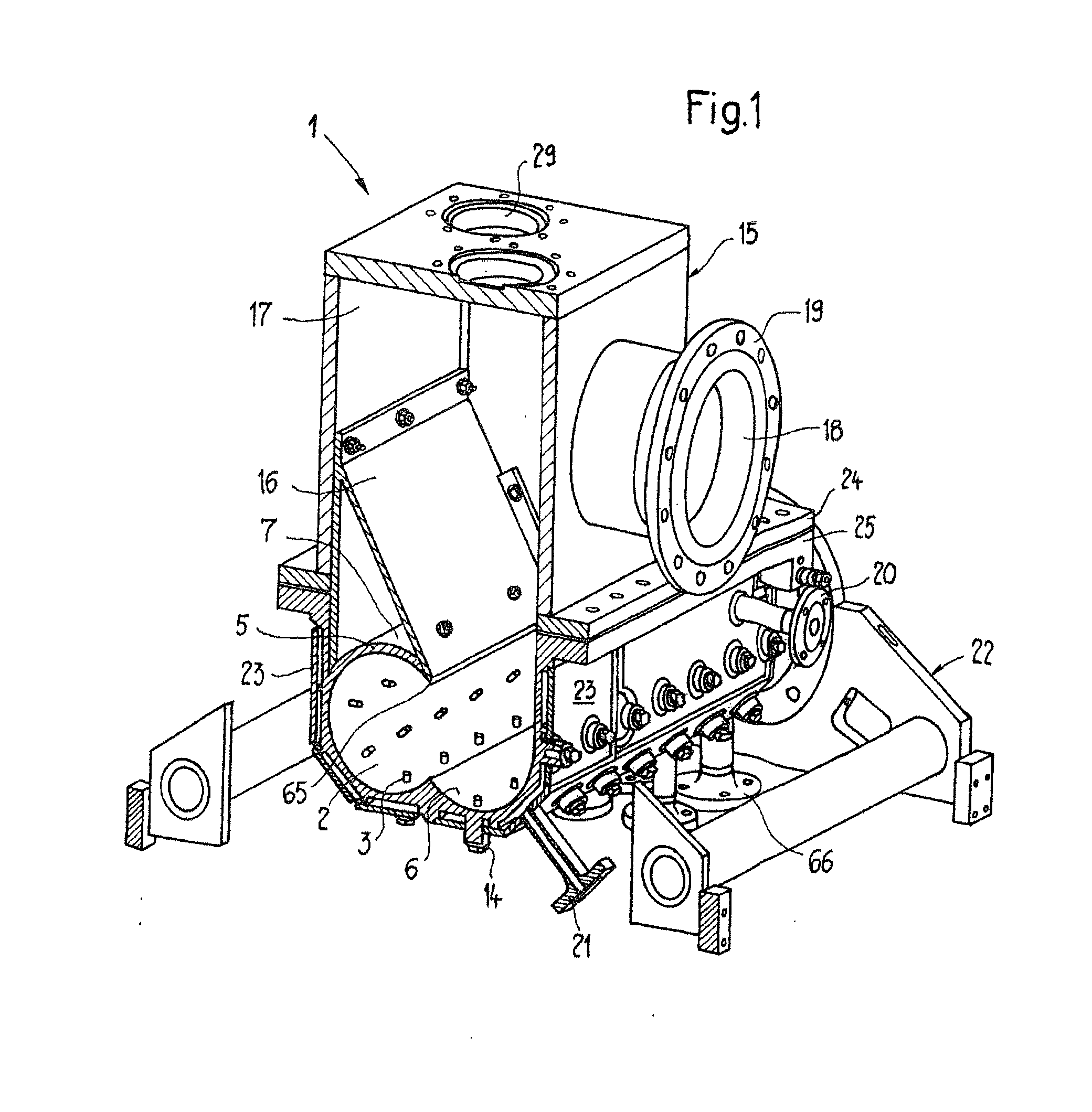
[0039]In FIG. 1 the inventive reactor / mixer is illustrated in a perspective view. In the shown embodiment, the housing 5 of the reactor / mixer 1 comprises a heating jacket 23 which at least partially encloses the latter. The heating jacket 23 comprises a heating medium inlet 20 and a heating medium outlet 21. The static mixing elements 3 are here mounted by means of pressure fittings 14 at the outside of the heating jacket 23 and protrude through respective openings in the wall of the housing 5 into the reaction chamber 2. However, also embodiments of the inventive reactor / mixer 1 without heating jacket 23 are conceivable. The inventive reactor / mixer 1 is supported in a reactor frame 22 and is connected by means of a flange-like projection 25 with a vapor collection space housing (i.e. in particular screwed together or welded), which in this regard comprises a corresponding flange-like protrusion 24. The vapor collection space housing 15 comprises at its upper side two openings 29, w...


PUM

PropertyMeasurementUnit
anglesaaaaaaaaaa
anglesaaaaaaaaaa
elasticaaaaaaaaaa

Abstract

An at least two shaft reactor/mixer, in particular for process engineering treatment of highly viscose, elastic and/or solid containing reaction substance and mixture, in which at the housing inner wall inwardly directed static mixing elements are arranged, which interact with scrapers of the at least two shafts in such a way, that in the area of the spaces between the scrapers the static mixing elements and the housing inner wall sheer forces, in particular a flow disturbance, are generated in an enhanced manner. In addition, there is a system including an end cap for a one or multiple shaft reactor/mixer and a discharge screw connector block being connectable with the end cap in a detachable manner.

Description

BACKGROUND OF THE INVENTION[0001]The present invention relates to an at least two shaft reactor / mixer, in particular for process engineering treatment—e.g. for devolatilization (degassing)—of highly viscose and / or solid-containing reaction substance and mixture as well as to a system including an end cap for a reactor / mixer and a discharge screw connector block being connectable with an end cap. This kind or reactors / mixers are applied for example in the production and processing of polymers and / or plastic materials as well as rubber and / or elastomers, i.e. in cases in which a good mixing effect and, if applicable, also a quick regeneration of free surfaces for the purpose of evaporating, respectively, devolatilization (degassing) shall be ensured. Further, such reactors / mixers should comprise a self-cleaning potential as good as possible, in order that as little as possible encrustation occurs at the reactor walls, respectively at the mixing instruments. This may namely lead to dis...

Claims


Application Information

Patent Timeline
Patent Type & Authority Applications(United States)
IPC IPC(8): B01F7/00
CPCB01F7/00975B01J19/20B01J2219/00058B01J2219/00094B01J2219/00162B01J2219/00186B29B7/481B29B7/845B29B7/86B01F27/091B01F27/1152B01F27/702B01F27/707B01F35/56B01F35/754551B01D19/0052B29B7/46
Inventor PETERS, HANSMOHR, STEFFEN
Owner BUSS SMS CANZLER
Why Eureka
Try Eureka