Lighting apparatus for visible light communication, and visible light communication system using the apparatus

Active Publication Date: 2014-10-30
PANASONIC INTELLECTUAL PROPERTY MANAGEMENT CO LTD
View PDF3 Cites 24 Cited by
  • Summary
  • Abstract
  • Description
  • Claims
  • Application Information

AI Technical Summary

Benefits of technology

[0005]It is an object of the present invention to provide a lighting apparatus for visible light communication and a visible light communication system using the apparatus, which can suppress generation of radiation noise and

Problems solved by technology

In the visible light communication system, when plural lighting apparatuses are located in a predetermined space and each lighting apparatus has a visible light communication function, communication signals transmitted from the lighting apparatuses may interfere with each other, and accordingly, there is a case where a receiver cannot accurately receive communication information.
However, the optical transmission system in the above-mentioned document needs to provide the lighting apparatus with the receiving unit configured to receive the communication signal, and accordingly, the cost for t

Method used


Image

  • Lighting apparatus for visible light communication, and visible light communication system using the apparatus
  • Lighting apparatus for visible light communication, and visible light communication system using the apparatus
  • Lighting apparatus for visible light communication, and visible light communication system using the apparatus

Examples


first embodiment

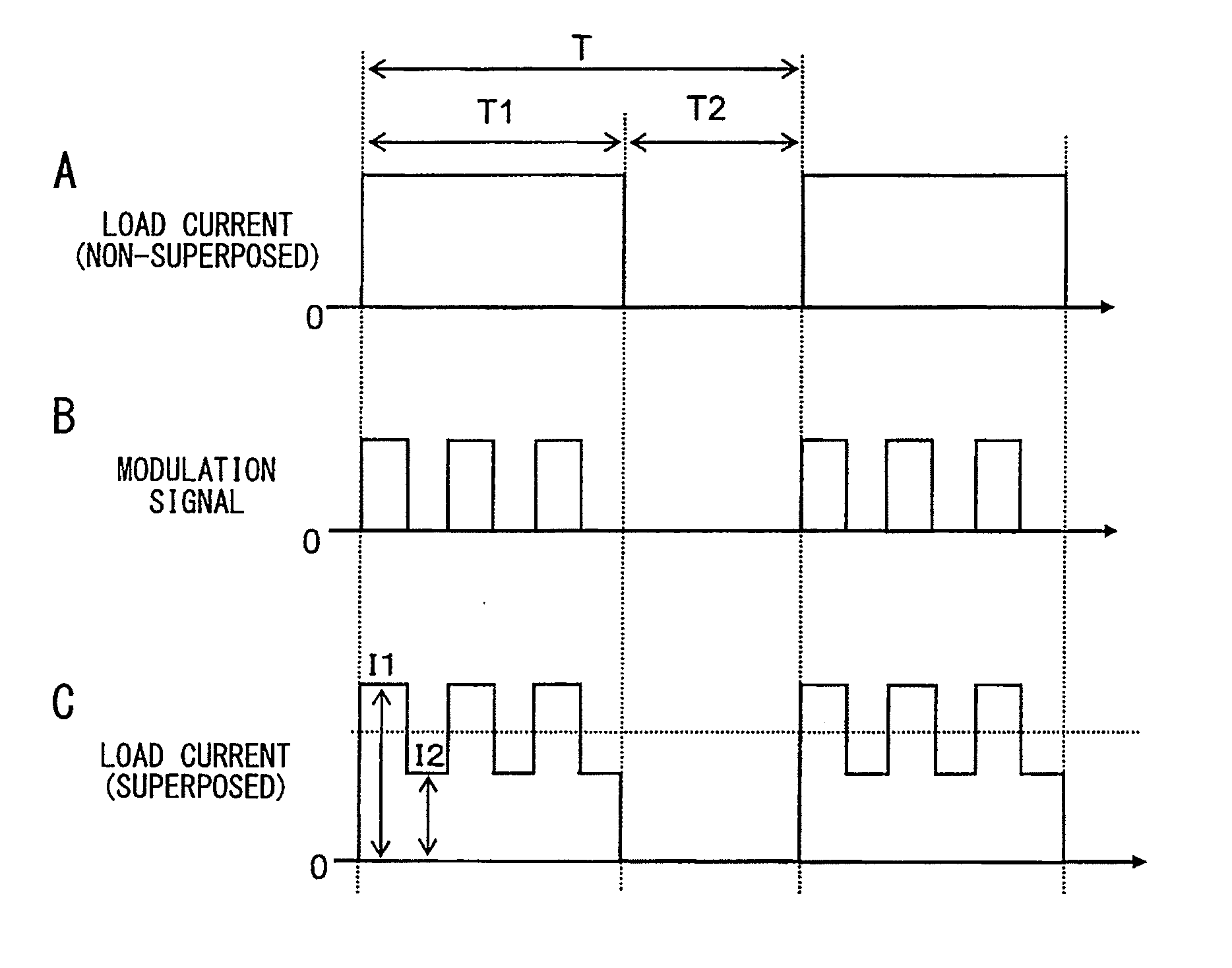
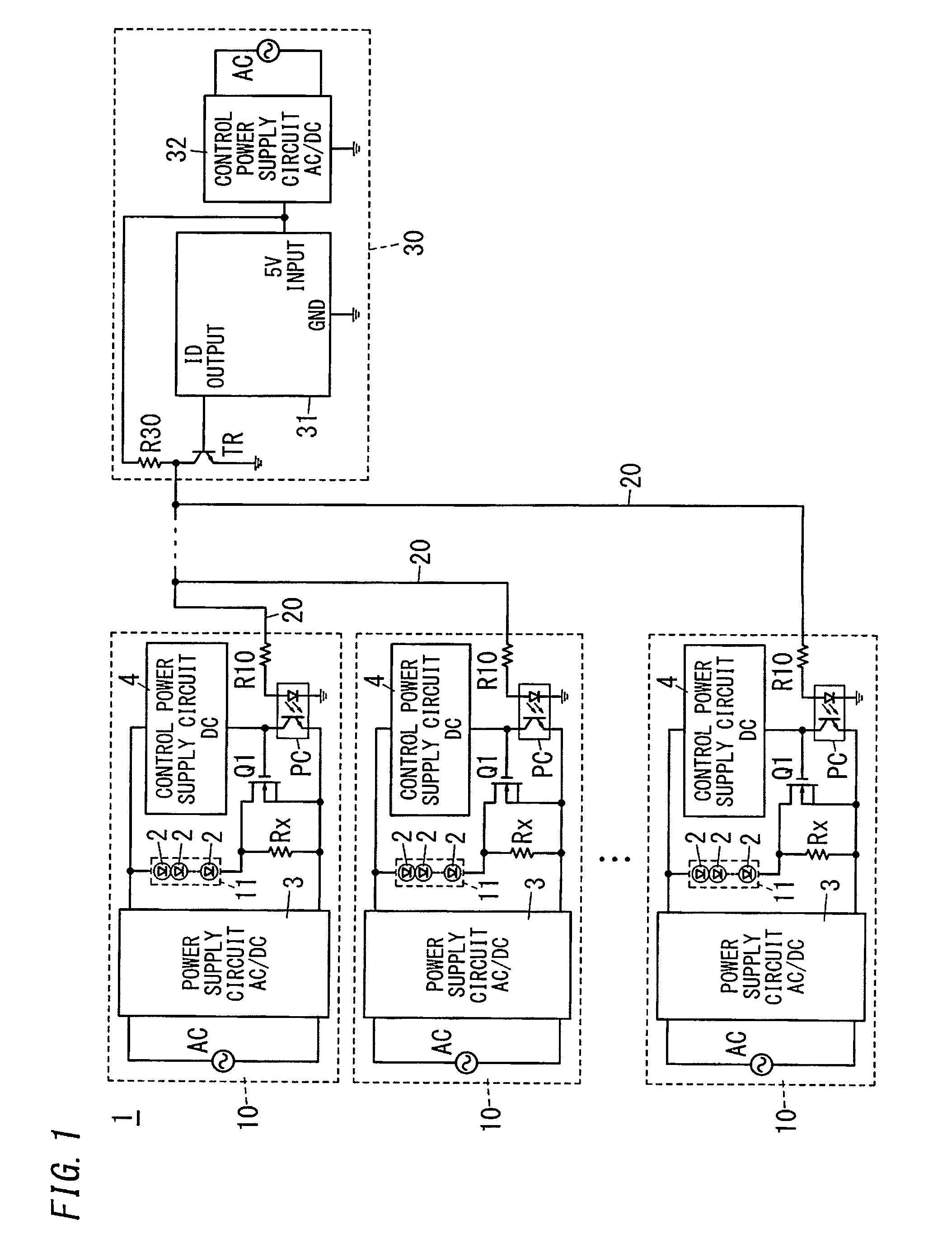
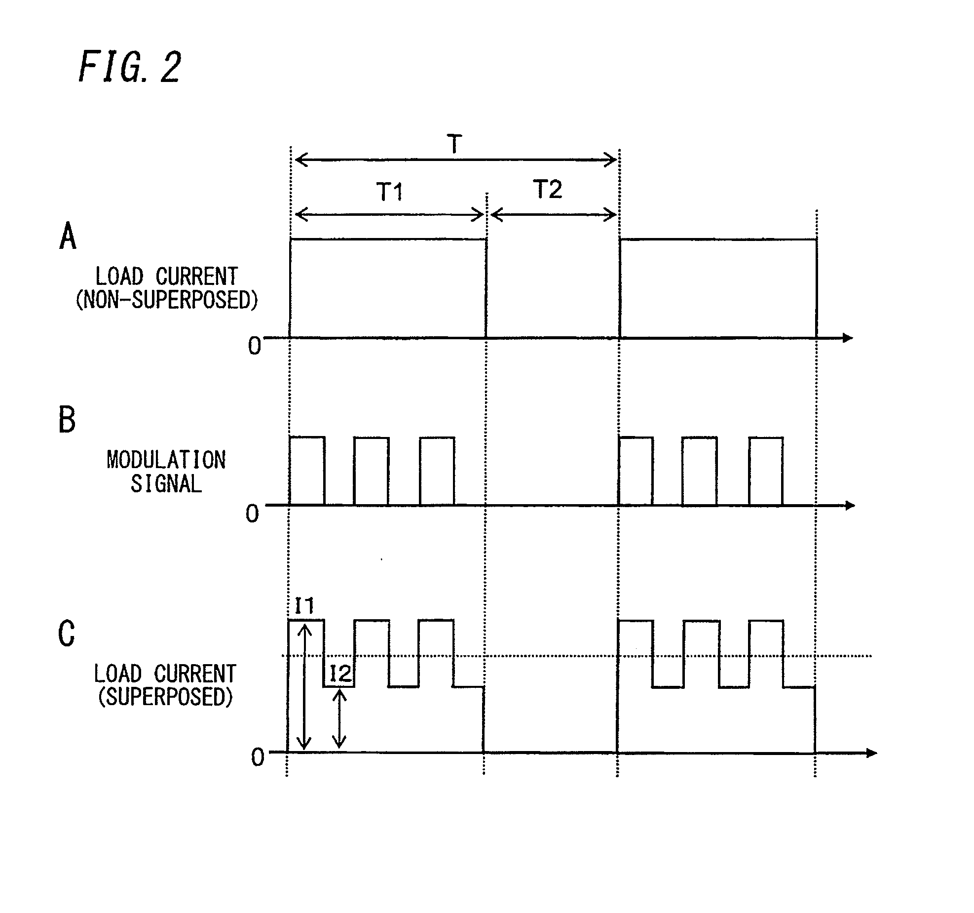
[0019]A lighting apparatus for visible light communication according to a first embodiment of the present invention will be described with reference to FIG. 1 and FIG. 2. As shown in FIG. 1, a lighting apparatus 1 for visible light communication of the present embodiment includes a plurality of luminaire bodies 10, and a visible-light-communication-signal-outputting part 30 that is connected to the plurality of luminaire bodies 10 via a plurality of signal lines 20 respectively. The visible-light-communication-signal-outputting part 30 is provided outside the plurality of luminaire bodies 10, and is configured to output a modulation signal for superposing a communication signal on illumination light emitted by a light source 11 of each luminaire body.

[0020]Each luminaire body 10 includes: the light source 11 including solid light-emitting elements (LEDs 2); and a lighting circuit configured to modulate light intensity of the illumination light emitted by the light source 11 and supe...

second embodiment

[0031]A lighting apparatus for visible light communication according to a second embodiment of the present invention will be described with reference to FIG. 3 and FIG. 4. As shown in FIG. 3, in a lighting apparatus 1 for visible light communication of the present embodiment, each luminaire body 10 further includes a high-frequency-signal-generating part 5 which is configured to output, to a switch element (for modulation) Q1, a high frequency modulation signal having a frequency that is higher than a frequency of a modulation signal transmitted from a visible-light-communication-signal-outputting part 30. Other configurations are similar to those of the above-mentioned embodiment.

[0032]The high-frequency-signal-generating part 5 of each luminaire body 10 (slave unit) divides, into plural subcarriers, a modulation signal (B of FIG. 4) transmitted from the visible-light-communication-signal-outputting part 30 (master unit) via a photo-coupler PC, and outputs a high frequency modulati...


PUM


Abstract

A lighting apparatus for visible light communication includes at least one luminaire body and a visible-light-communication-signal-outputting part. The luminaire body includes a light source that includes an LED. The visible-light-communication-signal-outputting part is configured to output a modulation signal to the luminaire body. The luminaire body further includes: a power supply circuit configured to dim the light source; a switch element for modulating an output current that is supplied from the power supply circuit to the light source; a resistor connected in parallel with the switch element; and a photo-coupler configured to receive the modulation signal output from the visible-light-communication-signal-outputting part. The visible-light-communication-signal-outputting part is provided outside the luminaire body, and is configured to transmit the modulation signal via the photo-coupler.

Description

TECHNICAL FIELD[0001]This invention relates to a lighting apparatus for visible light communication, configured to modulate light intensity of illumination light to superpose a communication signal on the illumination light, and a visible light communication system using the apparatus.BACKGROUND ART[0002]Conventionally, there has been known a visible light communication system, configured to transmit a communication signal with illumination light. In the visible light communication system, when plural lighting apparatuses are located in a predetermined space and each lighting apparatus has a visible light communication function, communication signals transmitted from the lighting apparatuses may interfere with each other, and accordingly, there is a case where a receiver cannot accurately receive communication information.[0003]In view of this, there has been known an optical transmission system, in which a receiver can accurately receive communication information even in such a spa...

Claims


Application Information

Patent Timeline
IPC IPC(8): H04B10/116H04B10/54H05B44/00
CPCH04B10/54H04B10/116H05B45/10H05B45/37H05B47/19
Inventor KIDO, SHOJIROUSHIOHAMA, EIJI
Owner PANASONIC INTELLECTUAL PROPERTY MANAGEMENT CO LTD
Why Eureka
Try Eureka