Quality control sensor method, system and device for use with biological/environmental rapid diagnostic test devices

a technology of quality control and sensor method, applied in the direction of thermometers, electric digital data processing, instruments, etc., can solve the problems of one or more inaccurate diagnostics, pre-analytical steps, reading errors,

Inactive Publication Date: 2014-10-30
FIO CORP
View PDF8 Cites 6 Cited by
  • Summary
  • Abstract
  • Description
  • Claims
  • Application Information

AI Technical Summary

Benefits of technology

[0073]Other advantages, features and characteristics of the present invention, as well as methods of operation and functions of the related elements of the system, method, and device and the combination of steps, parts and econ

Problems solved by technology

In the prior art, the use of rapid diagnostic tests (“RDTs”) may have been restricted and/or limited by inadequate, insufficient and/or lacking quality control (“QC”).
RDTs may be sensitive to and/or affected by temperature, pre-analytical steps, reading errors, and/or storage problems.
There may be a number of existing problems associated with RDTs, including, for example, the following:Temperature during shipping and/or storage may, from time to time, have been higher than an RDT's temperature specification, and/or a user of the RDT may not notice and/or pay sufficient heed to same, which may have led to one or more inaccurate diagnostic results.RDTs may need to be read at a specific time and/or within a specific time period.
In the field, however, the timers may be lost, and/or the user(s) of the RDTs may work on other RDTs during an assay time.
The assay time may not be accurately followed for one or more reasons, and/or it may be quite common to read an RDT too early and/or too late.
Such factors may also have led to inaccurate diagnostic results.In the field, doctors and/or nurses may have grouped patients together for RDTs when they have multiple patients.
However, it may have been very challenging to do so in the circumstances, perhaps due to multiple patients.
Providing for the continued w

Method used


Image

  • Quality control sensor method, system and device for use with biological/environmental rapid diagnostic test devices
  • Quality control sensor method, system and device for use with biological/environmental rapid diagnostic test devices

Examples


Embodiment Construction

[0076]Preferred embodiments of the quality control (“QC”) sensor system, method, and device according to the invention are alternately herein referred to, collectively and / or individually, as the QC system, method and / or device (or simply as the system, method and / or device). References to one or more of the QC sensor system, method and / or device may, if and as appropriate, be understood by persons having ordinary skill in the art to apply, mutatis mutandis, to the others.

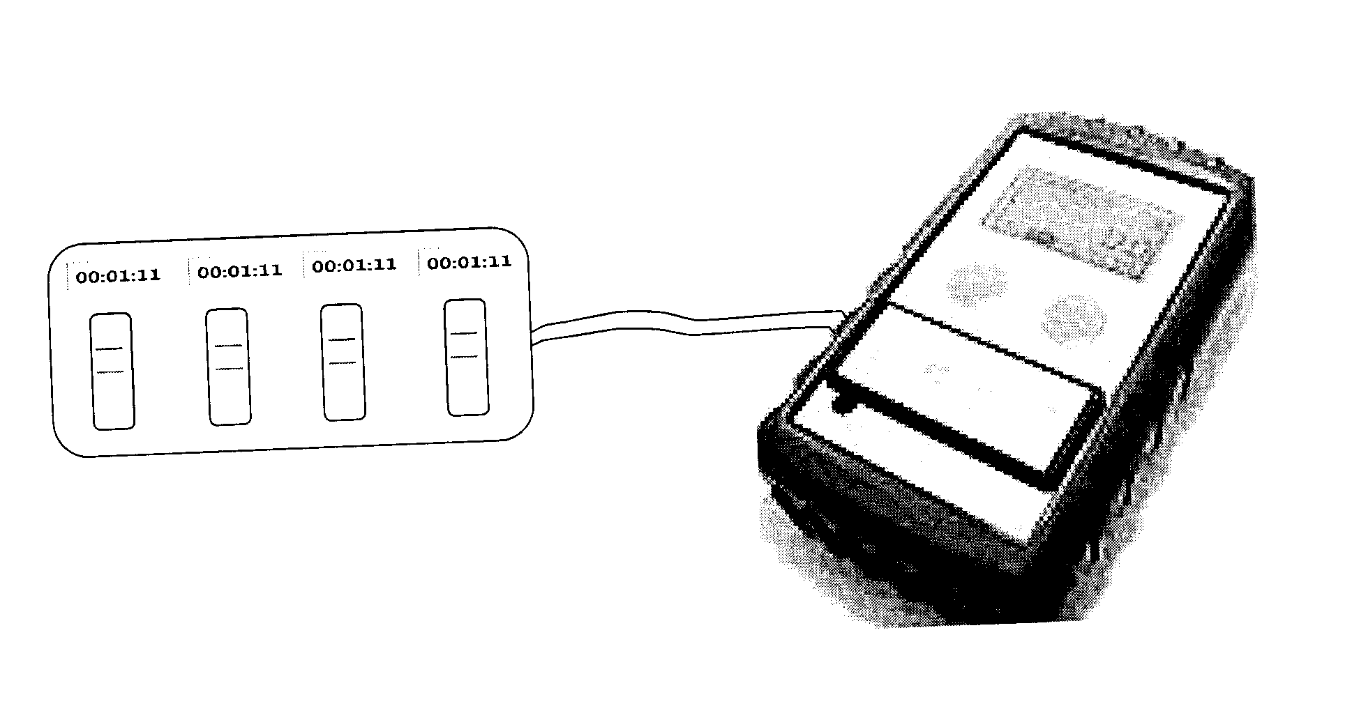
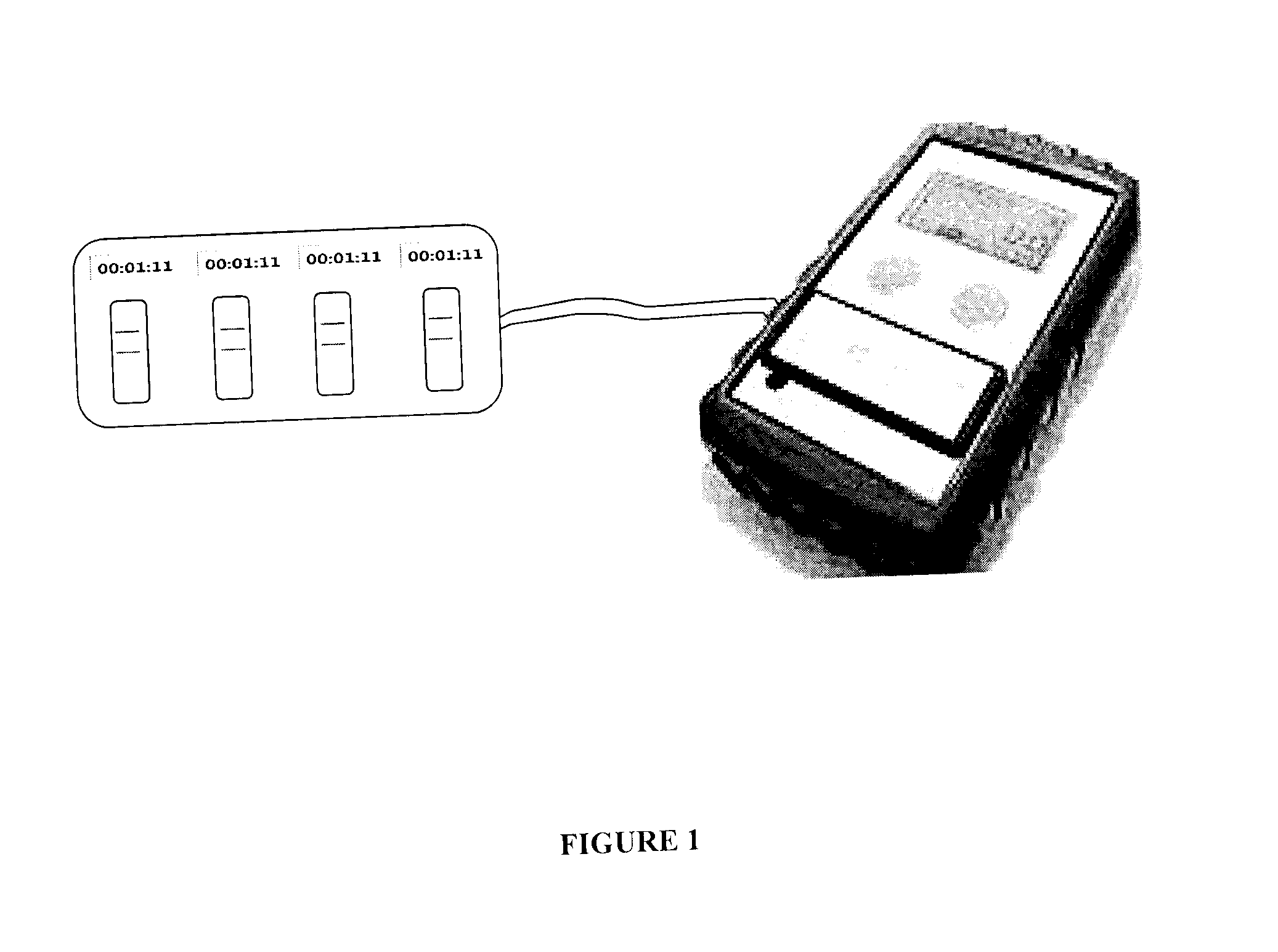
[0077]As aforesaid, the QC sensor system, method and device according to the invention are preferably for use with one or more biological and / or environmental rapid diagnostic test (“RDT”) devices. Each of the RDT devices has a RDT cassette bed. According to the invention, QC sensors are provided for QC of the RDT devices.

[0078]RDT cassettes are preferably provided with barcodes and / or radio frequency identification (“RFID”) chips which preferably encode cassette information associated with the cassettes. The casse...


PUM


Abstract

Quality control (QC) sensor methods, systems and devices are for use with biological/environmental rapid diagnostic test (RDT) devices and provide for automatic timers, reminders and RDT cassette images. Sensors are calibrated and optimized, and provide for quality control of the RDT devices. Image analysis identifies cassette and patient information, and evaluates the processing and conditions of the RDT devices, cassettes and RDTs. Results may be accessed and analyzed remotely from the RDT devices. RDT chain of custody and workflow, incubation and reading sequences are tracked. A QC score for each unique patient RDT is determined based on QC criteria.

Description

FIELD OF THE INVENTION[0001]The present invention relates generally to a quality control method, system and device, and more particularly to a quality control sensor method, system and device for use with biological / environmental rapid diagnostic test devices.BACKGROUND OF THE INVENTION[0002]In the prior art, the use of rapid diagnostic tests (“RDTs”) may have been restricted and / or limited by inadequate, insufficient and / or lacking quality control (“QC”).[0003]RDTs may be sensitive to and / or affected by temperature, pre-analytical steps, reading errors, and / or storage problems. There may be a number of existing problems associated with RDTs, including, for example, the following:[0004]Temperature during shipping and / or storage may, from time to time, have been higher than an RDT's temperature specification, and / or a user of the RDT may not notice and / or pay sufficient heed to same, which may have led to one or more inaccurate diagnostic results.[0005]RDTs may need to be read at a s...

Claims


Application Information

Patent Timeline
IPC IPC(8): G01N35/00
CPCG01N35/00623G01K11/12G01N33/48785
Inventor XIANG, QINGCHMURA, MICHAELFINE, IANGREENLAND, GRAHAMZASTAWNY, ROMAN
Owner FIO CORP
Why Eureka
Try Eureka