Plate heat exchanger and method for manufacturing a plate heat exchanger

Inactive Publication Date: 2014-11-06
VAHTERUS OY
View PDF10 Cites 4 Cited by
  • Summary
  • Abstract
  • Description
  • Claims
  • Application Information

AI Technical Summary

Benefits of technology

[0026]One advantage of the invention compared to the brazed heat exchanger constructions is that the heat exchange plates of the heat exchanger according to the invention are clear from filler or brazing materials and so the plates do not comprise any additional materials or barrier layers which weaken heat exchange properties. So, the manufacturing method of a heat exchanger according to the invention improves heat exchange properties. The completely welded structure of the invention also withstands high temperatures and rapid changes of temperatures better than the brazed heat exchangers known in the prior art.
[0027]The structure of the plate heat exchanger of the invention is completely welded, i.e. all elements of the heat exchanger are welded tightly to each other. Thus, one advantage of the invention is that the structure of the plate heat exchanger of the invention is simple, since it does not comprise any fastenings, sealings or gaskets between the elements, but they are replaced by the welded structures. The welded joints seam the strips arranged in the outer edge of the plate pack and the heat exchange plates together so that no separate fastenings or gaskets are needed, i.e. the structure of the heat exchanger of the invention is a non-gasket structure. The completely welded structure of the heat exchanger forms a compact pressure-proof element.
[0028]The pressure-proof outer surface of the heat exchanger of the invention is formed by arranging separate strips in the outer edge of the plate pack so that the outer surfaces of the strips and the outer edges of the heat exchange plates are substantially in the same plane, and by welding the strips and the outer edges of the heat exchange plates to each other. In an embodiment of the invention, the separate strips are arranged in the plate spaces of the plate pack. In a preferred embodiment of t

Problems solved by technology

A disadvantage in plate heat exchangers equipped with sealings has been their poor resistance especially to pressure, but also to temperature and corrosion.
The brazed structure withstands pressure quite well, but by r

Method used


Image

  • Plate heat exchanger and method for manufacturing a plate heat exchanger
  • Plate heat exchanger and method for manufacturing a plate heat exchanger
  • Plate heat exchanger and method for manufacturing a plate heat exchanger

Examples


Embodiment Construction

[0052]For the sake of clarity, the same reference numbers are used for corresponding parts in different embodiments.

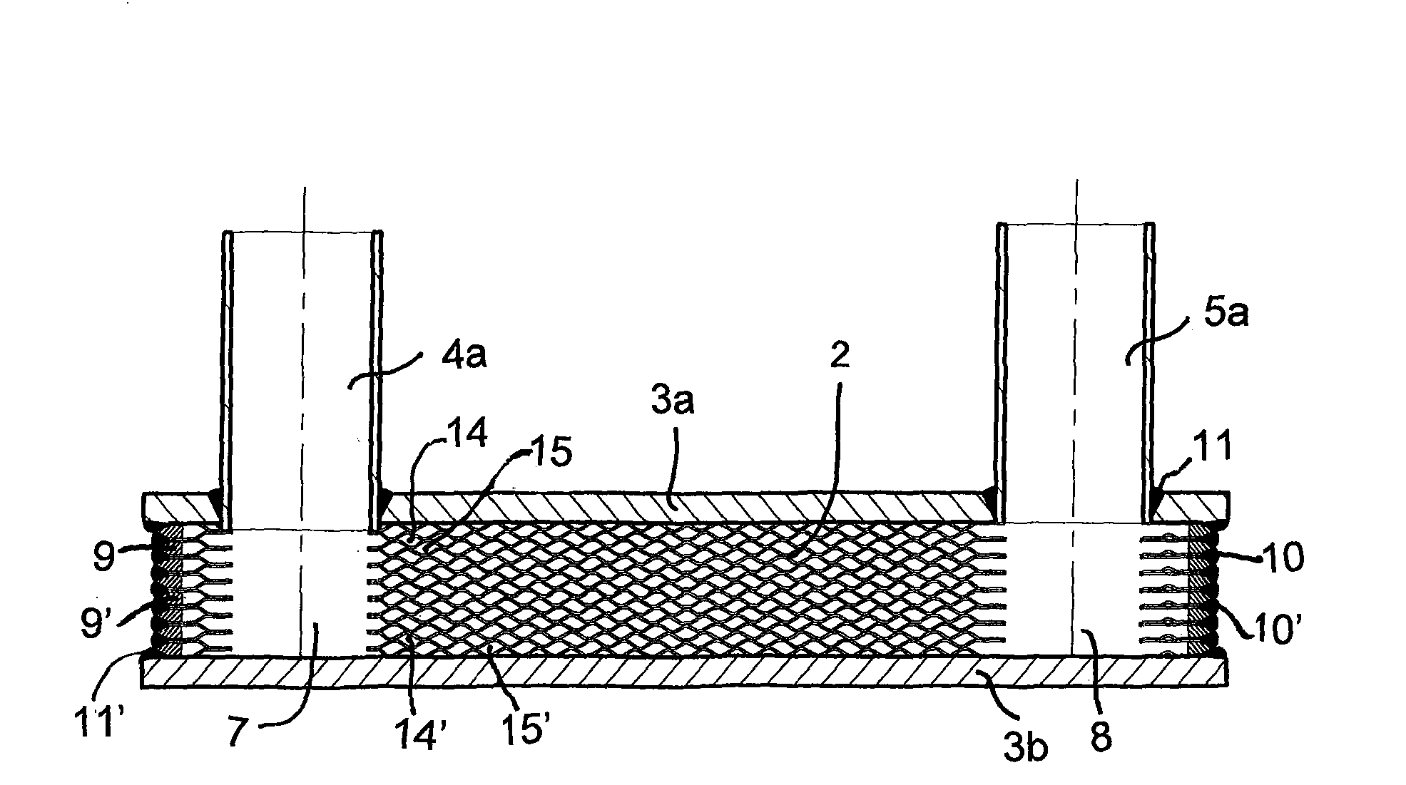
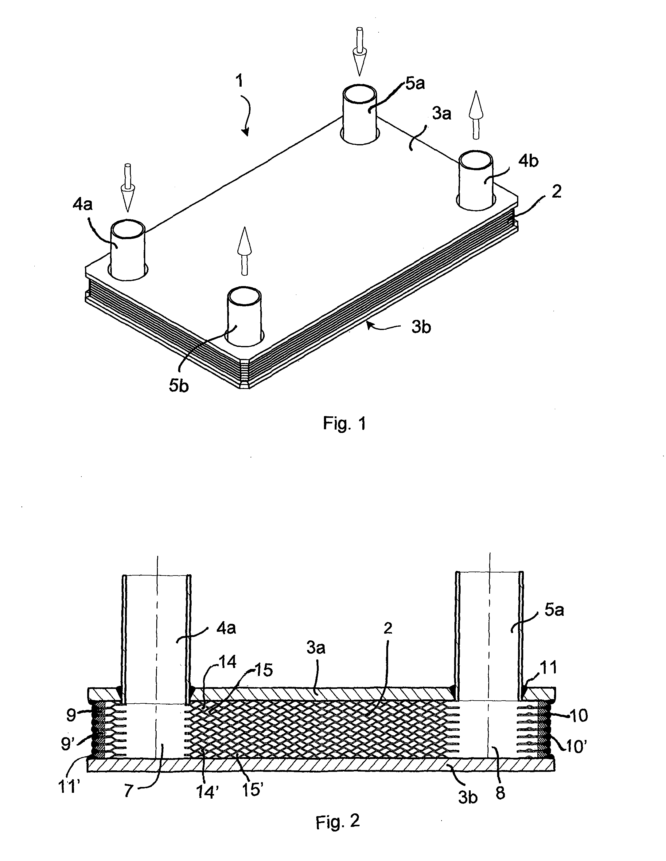
[0053]FIG. 1 shows a plate heat exchanger 1 according to an embodiment of the invention from outside. The plate heat exchanger 1 comprises a plate pack 2 formed by heat exchange plates and end plates 3a, 3b arranged under and over the plate pack 2 in connection with the uppermost and the lowest heat exchange plates. The inlet connection 4a and outlet connection 4b for the first heat exchange medium lead through the end plate 3a to the inside of the plate pack 2. The inlet connection 5a and outlet connection 5b of the second heat exchange medium also lead through the end plate 3a to the inside of the plate pack 2. The inlet and outlet connections 4a, 4b, 5a, 5b are arranged in connection with the flow channels of the plate pack 2. The flows of the first and the second heat exchange medium are shown with arrows in FIG. 1. A pressure-proof outer shell of the heat exchange...


PUM

PropertyMeasurementUnit
Thicknessaaaaaaaaaa
Widthaaaaaaaaaa
Structureaaaaaaaaaa

Abstract

The invention relates to a plate heat exchanger, which comprises a plate pack formed by corrugated heat exchange plates with openings for the flow of a first and a second heat exchange medium. The outer shell of the plate heat exchanger (1) has been formed by arranging separate strips (9, 9′) in the outer edge of the plate pack (2) so that the outer surfaces of the strips (9, 9′) are substantially in the same plane with the outer edges of the heat exchange plates (6, 6′), and by welding the strips (9, 9′) and the outer edges of the heat exchange plates (6, 6′) to each other.

Description

TECHNICAL FIELD OF THE INVENTION[0001]The invention relates to a plate heat exchanger and a method for manufacturing a plate heat exchanger according to the preambles of the independent claims presented below.BACKGROUND OF THE INVENTION[0002]In a typical prior art plate heat exchanger several rectangular heat exchange plates have been fastened on top of each other, the plates thus forming a plate pack. The plates of a plate heat exchanger are usually corrugated. The corrugation, i.e. the grooves and the ridges between them, aims to improve heat exchange properties and to cause a turbulent flow, which improves heat transfer coefficients. Typically, the plate pack is sealed with rubber sealing or the like, the sealings having been arranged in every plate space. Typically, the plate pack has been formed of heat exchange plates with openings, which openings form flow channels in the plate pack. The openings of the plate heat exchanger have been sealed in every other plate space, wherein...

Claims


Application Information

Patent Timeline
IPC IPC(8): F28D9/00B21D53/04
CPCF28D9/0037B21D53/04F28F3/10F28D9/005F28F2225/04Y10T29/49366
Inventor HEINIO, TAPIO
Owner VAHTERUS OY
Why Eureka
Try Eureka