Winding carrier for use in an electrical machine and winding arrangement

a technology for winding carriers and electrical machines, applied in the direction of windings, electrical apparatus, dynamo-electric machines, etc., can solve the problems of winding errors in the layer structure, disadvantage in the winding process, and cannot be prevented, so as to improve the heat dissipation of winding wires and simplify the production of orthocyclic layer structures

Active Publication Date: 2014-11-06
ROBERT BOSCH GMBH
View PDF8 Cites 15 Cited by
  • Summary
  • Abstract
  • Description
  • Claims
  • Application Information

AI Technical Summary

Benefits of technology

[0007]The object of the present invention is therefore to simplify the production of an orthocyclic layer structure during coil winding an...

Problems solved by technology

The groove structure, which has been used to date, with a semicircular cross section can lead to winding errors in the layer structure since the individual turns within the groove structure can shift due to pressure from further winding layers which are arranged further above it, in particular when the width of the groove structure is greater than the actual diameter of the winding wire.
This may result in the win...

Method used


Image

  • Winding carrier for use in an electrical machine and winding arrangement
  • Winding carrier for use in an electrical machine and winding arrangement
  • Winding carrier for use in an electrical machine and winding arrangement

Examples


Embodiment Construction

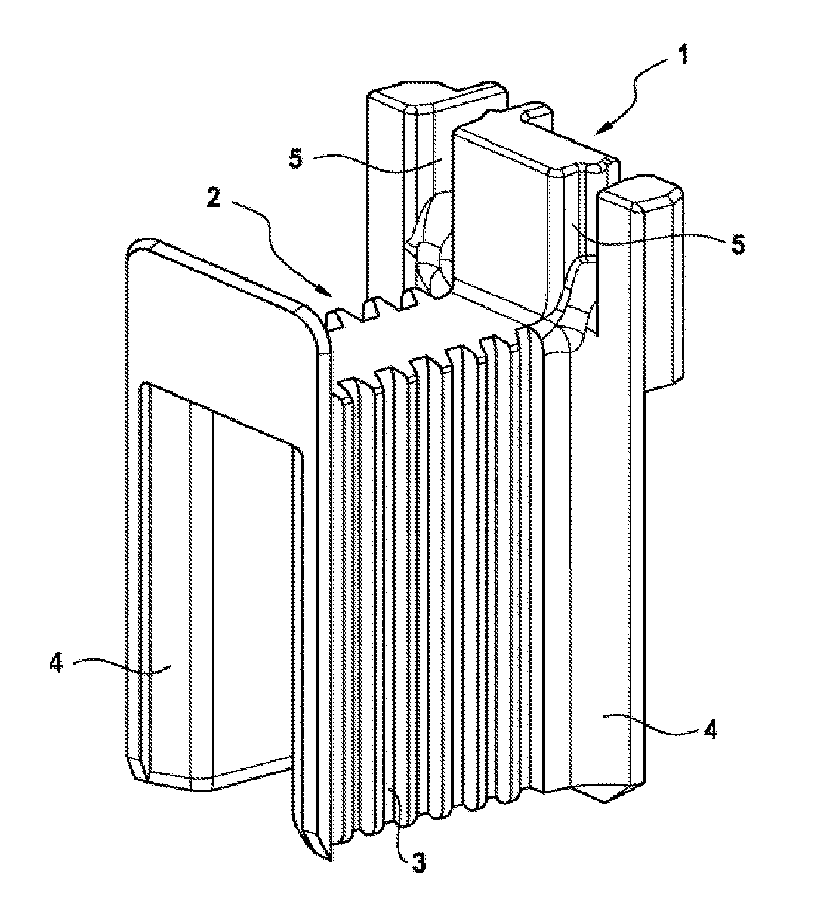
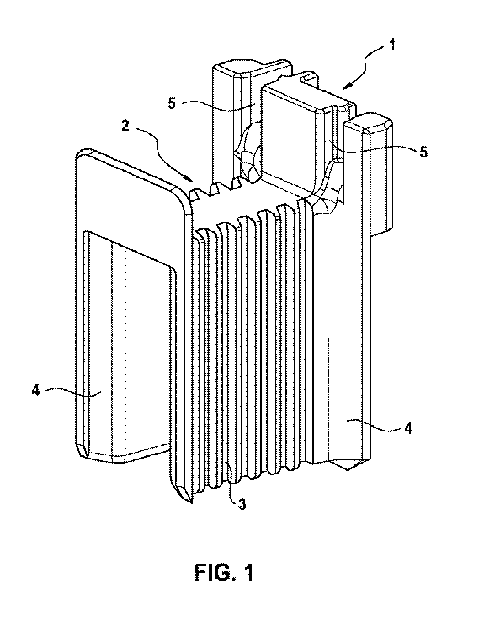
[0024]FIG. 1 shows a perspective illustration of a winding carrier 1 which is to be placed on a component tooth of an electrical machine. In particular, the winding carrier 1 can be placed on a stator tooth or a stator tooth segment in order to design a stator for an electrical machine. The winding carrier 1 is preferably formed from an electrically insulating material, such as plastic for example.

[0025]The winding carrier 1 can also have a cylindrical cross section, so that it can be pushed onto a component tooth in the axial direction. As an alternative, as illustrated in FIG. 1, the winding carrier 1 can be designed with an open side, so that it can be pushed laterally onto a component tooth, in particular when said component tooth has a widened tooth head. Two winding carriers of this kind can be placed onto the component tooth from opposite sides in order to completely insulate the component tooth from the winding.

[0026]The winding carrier 1 has a substantially cylindrical wind...


PUM


Abstract

The invention relates to a winding carrier (1) for the defined application of a coil winding, comprising: a winding section (2) for placing onto a cylindrical tooth component; a groove structure (3), which is arranged in at least one region of the winding section and extends transversely to the winding axis in order to receive a winding wire; wherein the groove structure (3) has a cross section having two mutually opposite, preferably flat side faces (7), which taper in the direction of a bottom face (6) of the groove structure (3).

Description

BACKGROUND OF THE INVENTION[0001]The present invention relates to electrical machines comprising coil windings which are fitted on component teeth with the aid of winding carriers. The present invention also relates to winding carriers for fitting a coil winding, in particular in the form of insulating laminations.[0002]Electrical machines generally have electromagnetic components which are designed in the form of coil windings. The coil windings are each wound around one or more teeth of a stator or of a rotor in order to generate an excitation magnetic field. In the case of coil windings around an individual component tooth, turns of the coil winding are fitted in a spiral manner, wherein the turns are arranged in several layers. A preferred arrangement of the turns is the so-called orthocyclic winding. In the case of an orthocyclic winding, the wires of one layer of the coil winding lie, by at least 30% of their circumference, in the valleys between the individual turns of the la...

Claims


Application Information

Patent Timeline
IPC IPC(8): H02K3/34
CPCH02K3/345H02K3/522H02K2203/12H02K2213/03
Inventor EWERT, ANDREASLEITZ, LUKASNOMMENSEN, BJOERN
Owner ROBERT BOSCH GMBH
Why Eureka
Try Eureka