
Method of investigating a solid sample

Active Publication Date: 2014-11-06
BERGEN TEKNOLOGIOVERFORIN AS
View PDF12 Cites 27 Cited by
  • Summary
  • Abstract
  • Description
  • Claims
  • Application Information

AI Technical Summary

Benefits of technology

The invention is a method and device for high-resolution imaging of samples, such as borehole cores, using a sample support device and a hyperspectral camera device. The mutual movement of the sample support device and the hyperspectral camera device allows for precise positioning of the sample and reduces imaging artifacts. The device can provide an additional topological image of the sample, which may help identify missing parts of the sample. The high-resolution mapping of materials and geological features allows investigation of potential correlations with petrophysical properties, while the portable apparatus allows for on-site imaging without transporting the sample. The use of a fixed position for the at least one electrical light source and the hyperspectral camera device increases stability and accuracy of the illumination conditions. This invention provides a better and faster way to obtain high-quality images of samples.

Problems solved by technology

However, as a general disadvantage of the conventional techniques for investigating borehole cores, the acquisition of data is extremely costly and time consuming.
As a main disadvantage, these sub-sampling procedures and analysis commonly damage or destroy the core material.
Furthermore, they provide properties of the core at single positions only, but they do not allow a continuous mapping of the core material or a precise prediction of material properties, like e.g. the material composition or distribution of sample components.
However, the use of a scanning interferometer represents a disadvantage in terms of the complexity of the interferometer and the operation thereof as well as with regard to the complex processing of the interferometric spectral data.
The conventional approach has disadvantages due to a restricted spatial resolution and a limited capability of determining the presence of different materials.
Furthermore, the practical application of the hyperspectral imaging technique may result in substantial imaging artifacts and problems with regard to image interpretation.

Method used


Image

  • Method of investigating a solid sample
  • Method of investigating a solid sample
  • Method of investigating a solid sample

Examples


Embodiment Construction

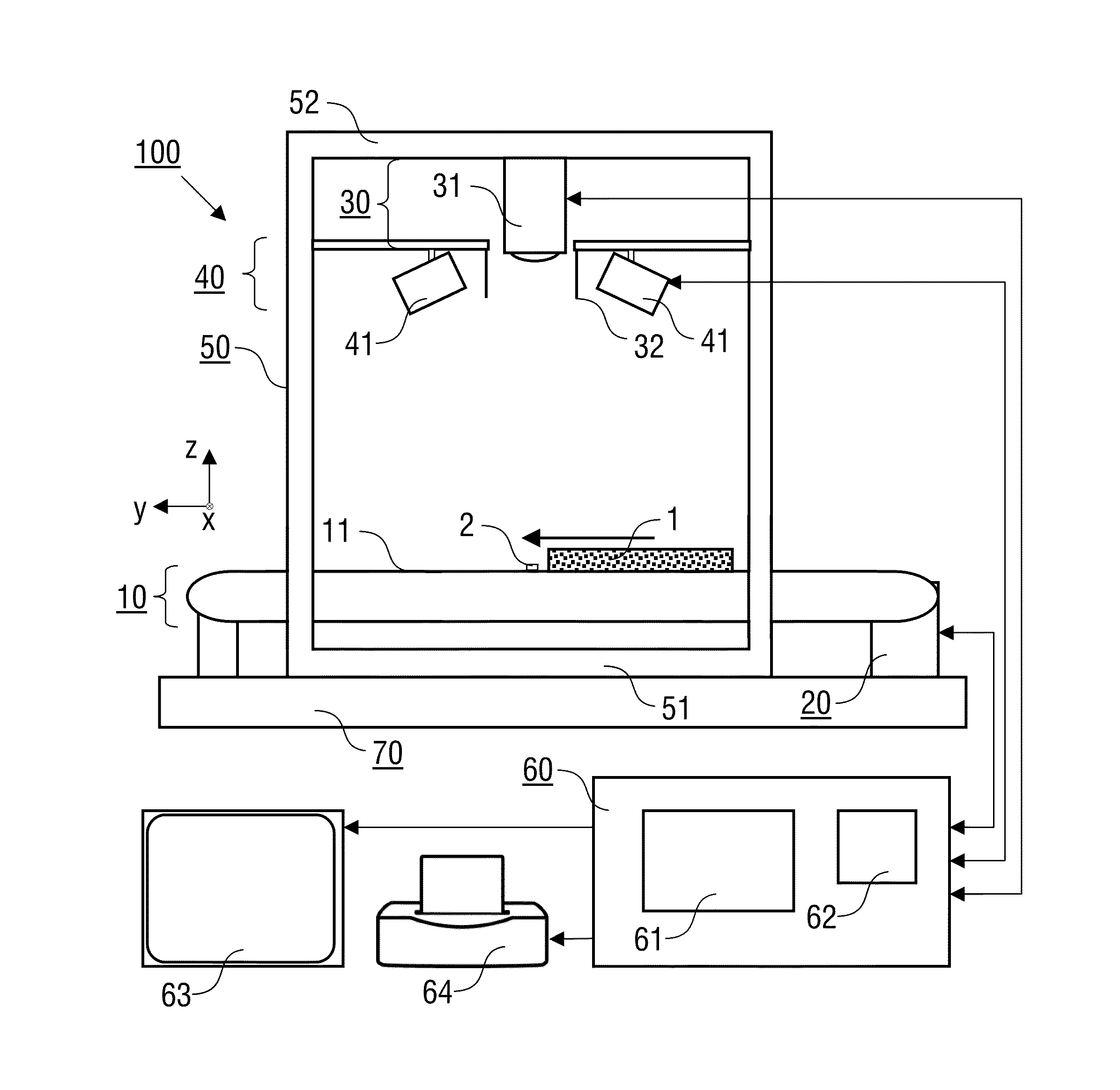
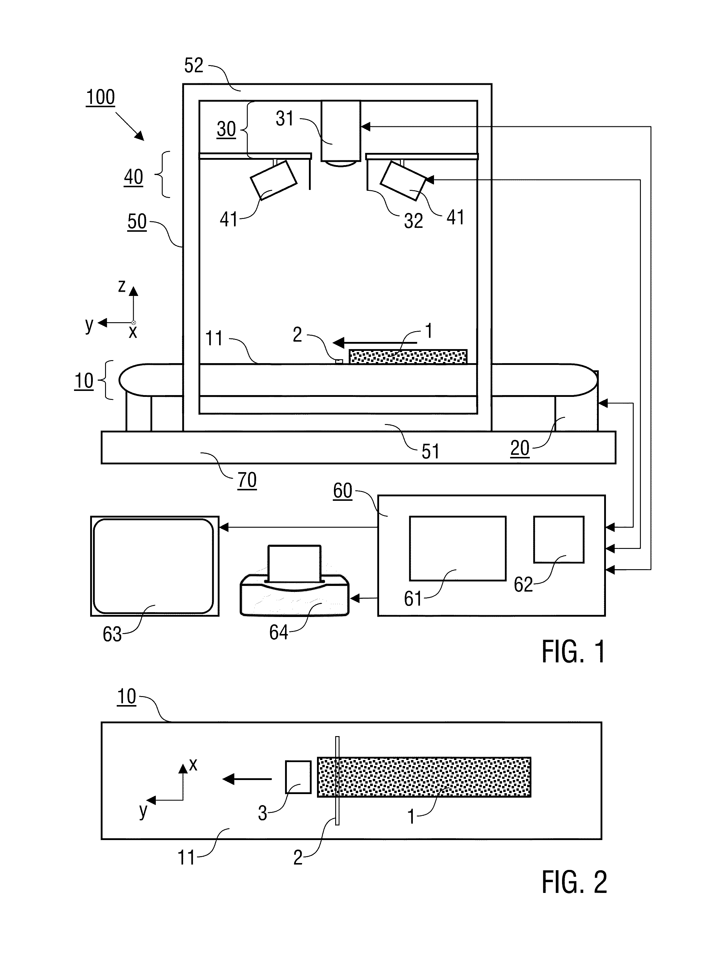
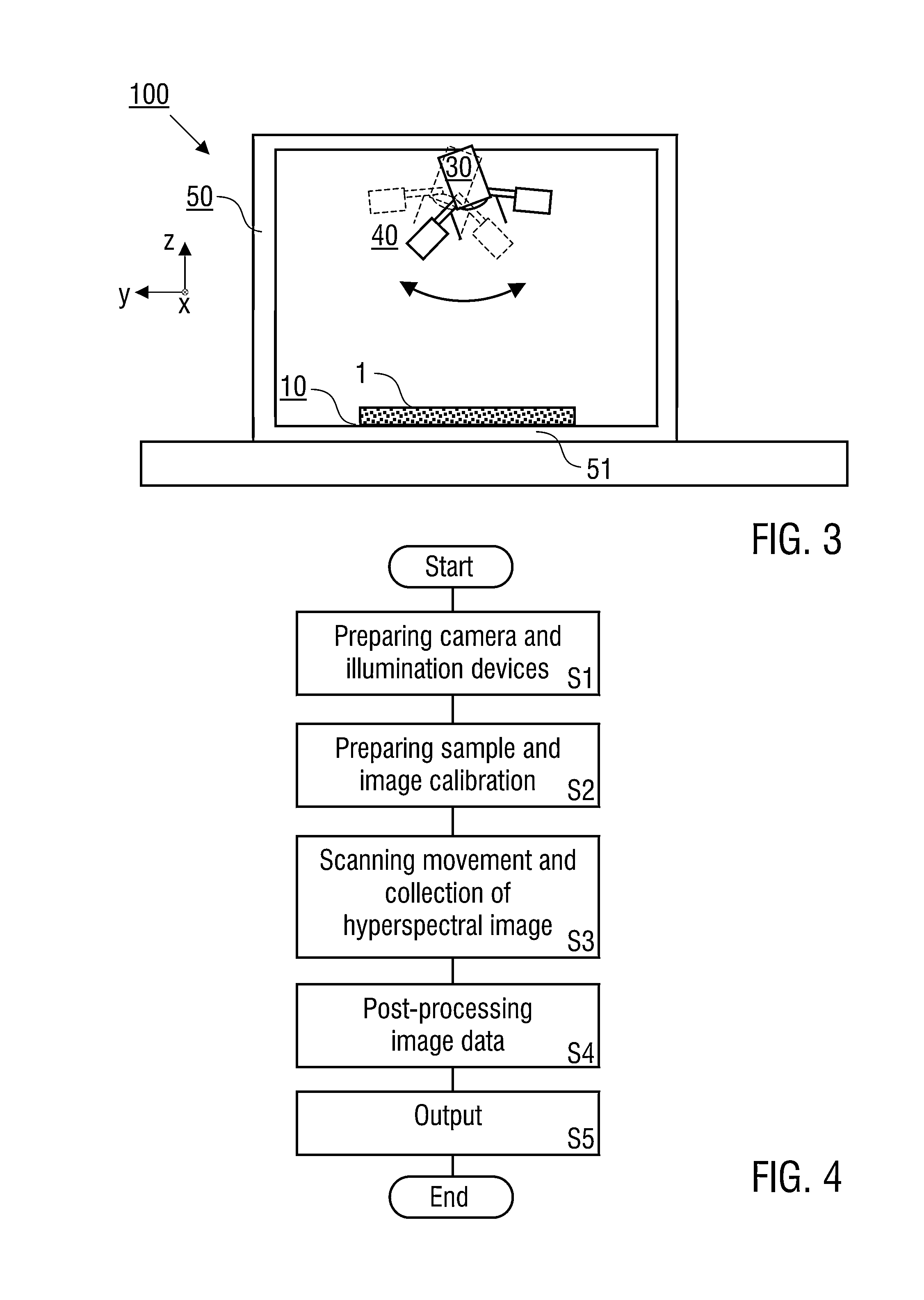
[0036]Preferred embodiments of the invention are described in the following with particular reference to the arrangement of the hyperspectral camera device and the sample support device, the implementation of the relative movement thereof, the illumination of the sample and the collection of hyperspectral images. Details of the hyperspectral camera device are not described as far as they are known from commercially available hyperspectral cameras. Furthermore, details of the processing of the hyperspectral images and the evaluation of spectral properties of a sample are not described as far as they are known from conventional applications of hyperspectral cameras.

[0037]In the following, reference is made in an exemplary manner to an application of the invention, wherein borehole core samples are investigated. It is emphasized that the implementation of the invention is not restricted to this type of samples, but rather possible with other types of solid samples, in particular other ...


PUM


Abstract

A method of investigating a solid sample, in particular a geological sample, such as a borehole core sample, includes the steps of positioning the sample on a sample support device, positioning a hyperspectral camera device, so that a line-shaped surface region of the sample is covered by a field of view of the hyperspectral camera device, illuminating the sample on the sample support device, moving the hyperspectral camera device and the sample support device relative to each other, wherein the field of view of the hyperspectral camera device is moved along a scanning direction over the surface of the sample, and collecting a hyperspectral image of the sample during the moving step, wherein the hyperspectral image is composed of multiple hyperspectral line images.

Description

FIELD OF THE INVENTION[0001]The invention relates to a method of investigating a solid sample using hyperspectral imaging, in particular to a method of investigating solid geological samples, such as borehole core samples. Applications of the invention are available in the fields of analyzing geological samples, like e.g. borehole cores, or other solid materials, like workpieces, paper or food.TECHNICAL BACKGROUND OF THE INVENTION[0002]It is generally known that extracting cores from oil exploration boreholes is a routine way of sampling and assessing hydrocarbon reservoirs. Borehole cores provide a unique inside into lithology and mineralogy of the subsurface. However, as a general disadvantage of the conventional techniques for investigating borehole cores, the acquisition of data is extremely costly and time consuming. Conventionally, collected cores routinely undergo multiple analyses aimed at describing the mineral composition and petrophysical (rock physics) properties of the ...

Claims


Application Information

Patent Timeline
IPC IPC(8): G01N21/25H04N5/33
CPCH04N5/332G01N21/255G01J3/2823G01N21/31G01V8/20G01V99/00H04N23/11
Inventor KURZ, TOBIAS HERBERTBUCKLEY, SIMON JOHNHOWELL, JOHN ANTHONY
Owner BERGEN TEKNOLOGIOVERFORIN AS
Learn More