Eureka AIR delivers breakthrough ideas for toughest innovation challenges, trusted by R&D personnel around the world.

Antireflection film

Inactive Publication Date: 2014-11-06
FUJIFILM CORP
View PDF6 Cites 4 Cited by
  • Summary
  • Abstract
  • Description
  • Claims
  • Application Information

AI Technical Summary

Benefits of technology

The present invention provides an antireflection film that can reduce reflectance in a wavelength range near a design wavelength and has a stable structure that can be formed in a simple manner. The film can be used in the visible light range to further reduce reflectance around green light, which is highly visible to human eyes. The film thicknesses set as shown by the conditional expressions allow reducing the film thicknesses. The structure of the antireflection film of the invention can be made to have a low aspect ratio when compared to a moth-eye structure, which provides high mechanical strength and improves manufacturing suitability.

Problems solved by technology

However, this antireflection film also has the problem of increase of reflection when the wavelength of incoming light deviates from a design wavelength, and has a narrow antireflection band.
However, such an antireflection film has a drawback that the reflectance increases when light enters obliquely.
This type of antireflection film, however, requires a certain film thickness, and has a weak mechanical strength, resulting in an unstable structure.

Method used


Image

  • Antireflection film
  • Antireflection film
  • Antireflection film

Examples


Embodiment Construction

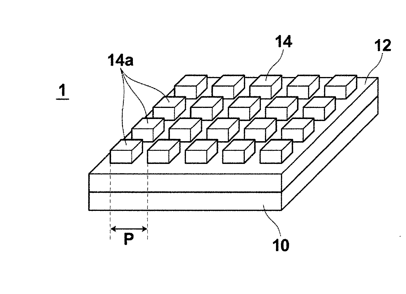
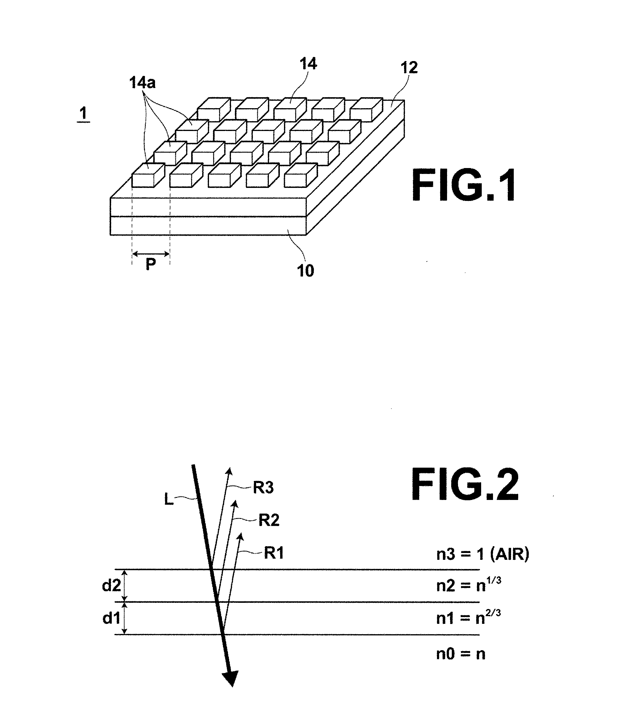
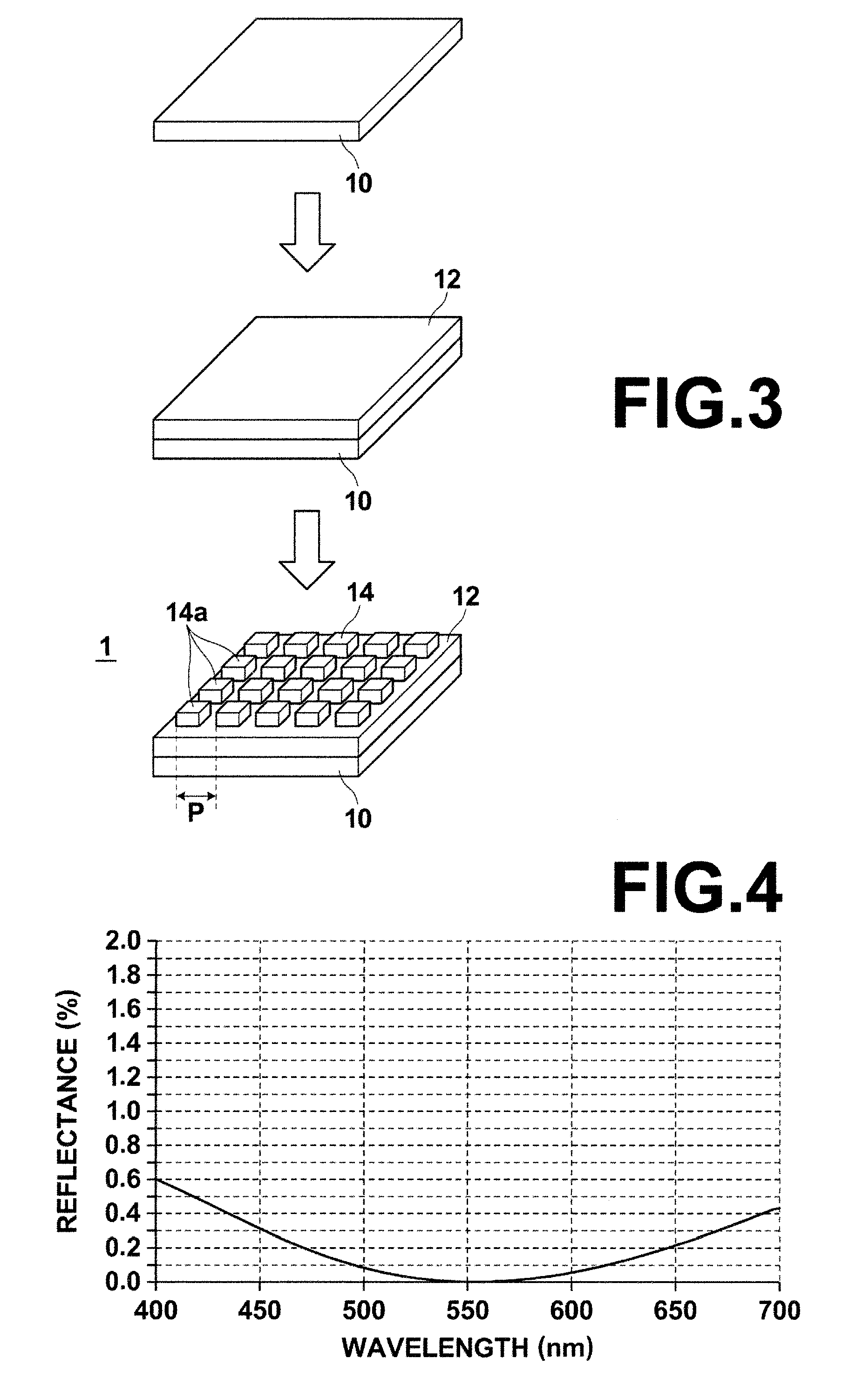
[0032]Hereinafter, one embodiment of an antireflection film of the present invention will be described in detail with reference to the drawings. FIG. 1 illustrates the schematic structure of an antireflection film of this embodiment.

[0033]As shown in FIG. 1, an antireflection film 1 of this embodiment includes, on a transparent glass substrate 10, a first layer 12 and a second layer 14 formed in this order from the glass substrate 10 side.

[0034]First, the basic design concept of the antireflection film 1 of this embodiment is described using FIG. 2. The antireflection film 1 of this embodiment is configured such that average refractive indices of the first layer 12 and the second layer 14 at a design wavelength λ0 decrease in geometric progression from the glass substrate 10 side toward an ambient medium (for example, air) on the light entrance side. Specifically, as shown in FIG. 2, assuming that the glass substrate 10 has a refractive index n0=n and the ambient medium (air) in con...


PUM

PropertyMeasurementUnit
Thicknessaaaaaaaaaa
Areaaaaaaaaaaa
Wavelengthaaaaaaaaaa

Abstract

An antireflection film includes a first layer and a second layer formed on a substrate in this order from the substrate side, the second layer being formed to be in contact with an ambient medium. The first layer and the second layer are formed such that an average refractive index n1 of the first layer at a given wavelength λ0, an average refractive index n2 of the second layer at the given wavelength λ0, a film thickness d1 of the first layer, and a film thickness d2 of the second layer satisfy conditional expressions below:0.96<n1 / (n0×n0×n3)1 / 3<1.04, 0.96<n2 / (n0×n3×n3)1 / 3<1.04, 0.8<d1×n1 / (λ0 / 6)<1.2, and0.8<d2×n2 / (λ0 / 6)<1.2, where n0 is a refractive index of the substrate at the given wavelength λ0, and n3 is a refractive index of the ambient medium at the given wavelength λ0.

Description

CROSS-REFERENCE TO RELATED APPLICATIONS[0001]This application is a Continuation of PCT International Application No. PCT / JP2013 / 000280 filed on Jan. 22, 2013, which claims priority under 35 U.S.C §119 (a) to Japanese Patent Application No. 2012-011634 filed on Jan. 24, 2012. Each of the above applications is hereby expressly incorporated by reference, in its entirety, into the present application.TECHNICAL FIELD[0002]The present invention relates to an antireflection film having a two-layer structure including a first layer and a second layer formed on a substrate.BACKGROUND ART[0003]Conventionally, reflection on surfaces of optical elements cause decrease of light transmittance of lenses, etc., ghost or flare, reflection of external light on display screens, etc., and therefore high-performance antireflection is desired.[0004]As a method for achieving such antireflection, a method where a multi-layer film having a single-layer, two-layer, three-layer or more layer structure is form...

Claims


Application Information

Patent Timeline
IPC IPC(8): G02B1/11G02B1/111G02B1/118
CPCG02B1/11G02B1/111G02B1/118
Inventor TANI, TAKEHARU
Owner FUJIFILM CORP
Why Eureka
Eureka Blog
Learn More