Method for operating a communications network and network arrangement

a communication network and network arrangement technology, applied in the field of communication network and network arrangement, can solve problems such as network infrastructure overloaded, nodes in the network being used are faulty, inconsistent data errors,

Active Publication Date: 2014-11-06
SIEMENS AG
View PDF5 Cites 6 Cited by
  • Summary
  • Abstract
  • Description
  • Claims
  • Application Information

AI Technical Summary

Benefits of technology

[0023]The monitoring of the data transmission rate and the potential blocking of data reception make it possible to handle, in particular, what are referred to as “Babbling Idiots”, that is to say network devices present in the network which due to a defect transmit meaningless data or data which cannot be interpreted by other devices in the network.
[0076]Overall, a particularly reliable network arrangement, which functions reliably even in the case of disruptions of communication channels is obtained. The redundant ring-shaped communication path device permits consistent control device communication and fault analysis and correction which are favorable in terms of expenditure and handling of faults due to Babbling Idiots in a way which is favorable in terms of expenditure.

Problems solved by technology

In this respect, errors in the form of inconsistent data, which may be corrupted, for example, in the case of data transmission via the network which is being used, have to be detected.
Furthermore it is possible that nodes in the network being used are faulty.
The network infrastructure can be overloaded by high data rates in such a way that genuine control data or sensor data can no longer be exchanged between the still functioning network devices.
In the past, methods were proposed in which the data exchange between predefined communication partners was bandwidth-limited.
Defective network nodes can, however, also generate data packets with inadequate address data, and within the scope of a dedicated bandwidth limitation this cannot be handled satisfactorily in every network topology, in particular not in a ring-shaped network topology.
Such timeslot methods require complex synchronization and special hardware devices.
This “meaningless” data is often output at high frequency by the faulty devices, with the result that the network infrastructure and communication paths can become overloaded.
In this respect, redundant forwarding and checking of the functional capability of all the network devices involved becomes possible.

Method used


Image

  • Method for operating a communications network and network arrangement
  • Method for operating a communications network and network arrangement
  • Method for operating a communications network and network arrangement

Examples


case 4

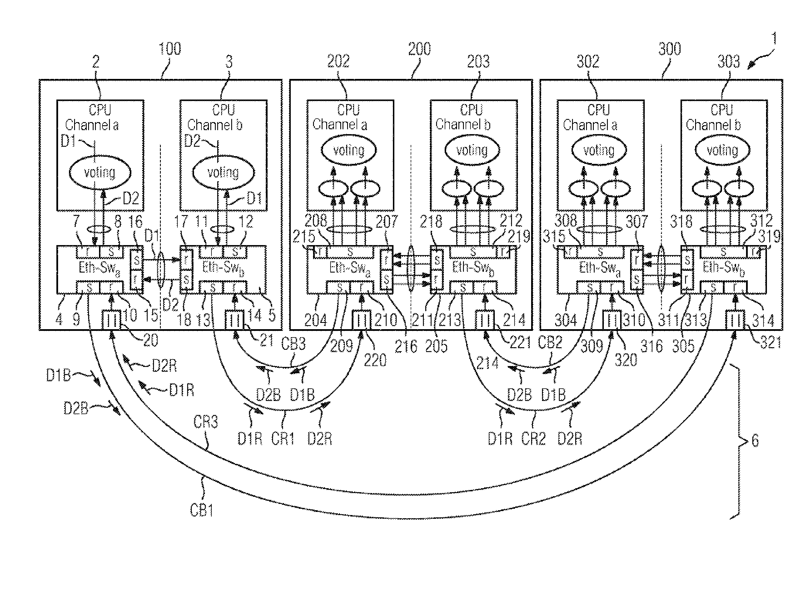
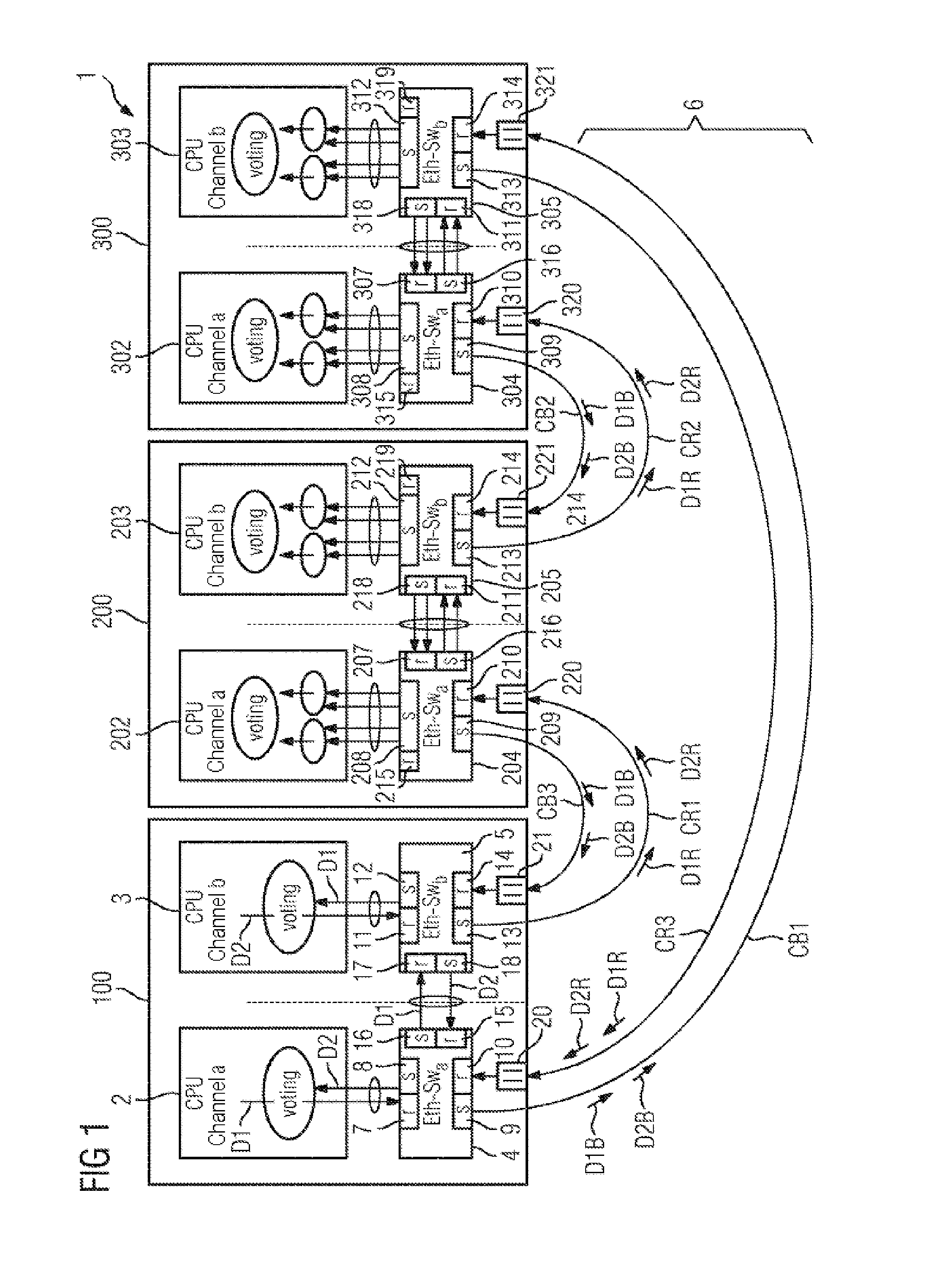
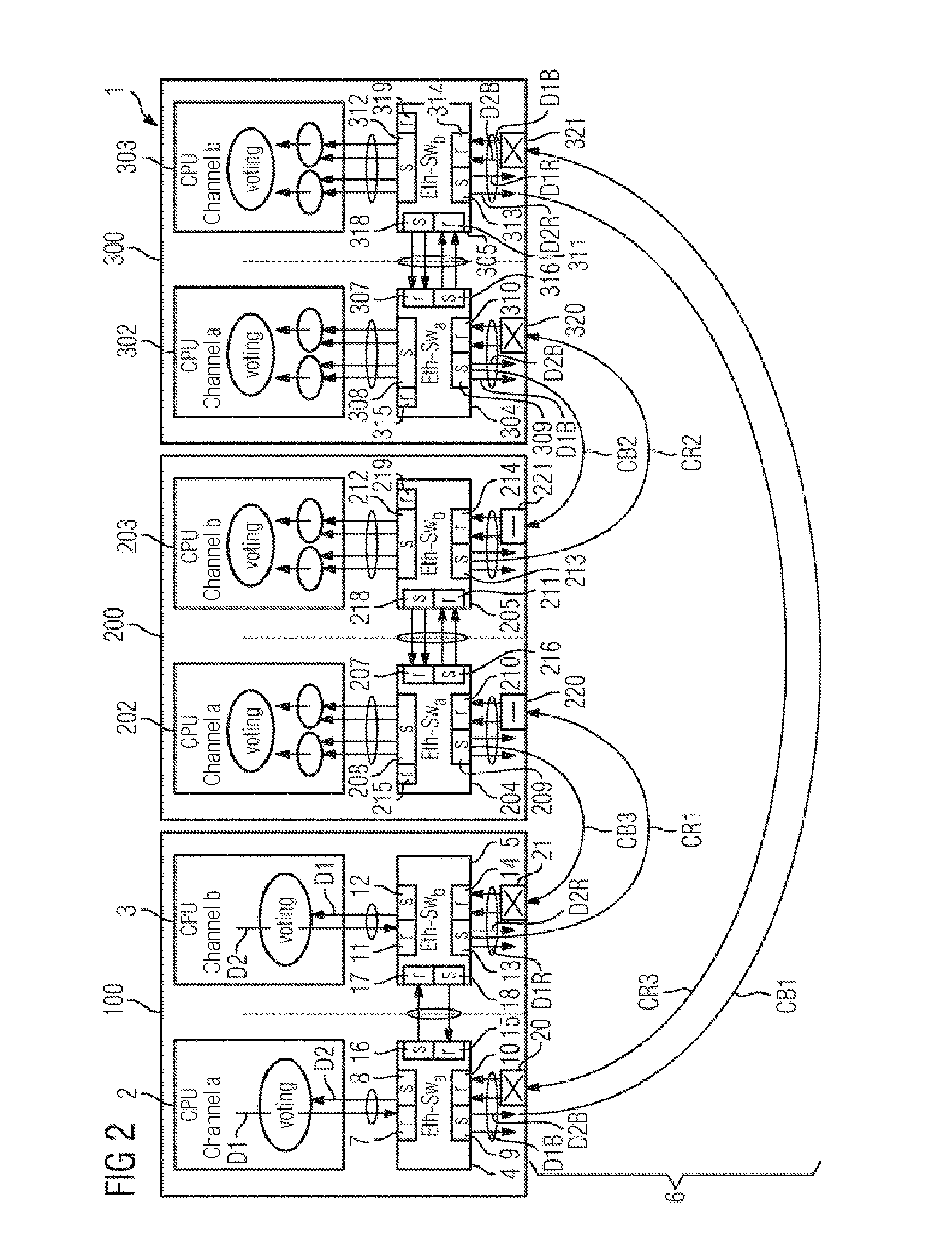
[0182]The network device 832 babbles with a bandwidth of more than 80%. The fuse F4 of the control computer 814 and the fuse F5 at the network device 822 trigger. The network device 832 is therefore disconnected from the communication but the rest of the communications network 102 is not adversely affected. Only the redundancy in the right-hand outer ring is lost. The network device 822 is not lost either in this case 4.

[0183]The second example is based on the assumption that the control computer 811 is the Babbling Idiot. Here, three cases can be differentiated:

case 1

[0184]The control computer 811 babbles with a low bandwidth. One of the fuses F5 between the network devices 831 and 822 possibly triggers, since here a low permissible bandwidth (F5=10%) is set. This effect is undesired but does not lead to the loss of a network device but instead only to the loss of the redundancy in the right-hand outer ring composed of the segments 704 and 705. The fuses which could separate the outer rings from the outer ring port F5 of the control computer lying opposite do not trigger, since the packets transmitted on to the outer ring have to be associated with the VLAN V1 or the VLAN V2. Data packets which are transmitted by the one control computer 811 are not received by the other control computer 813 under any circumstances, since the other control computer 813 is always associated with the other VLAN V2, V1. No network device and no control computer is therefore excluded from the communication and the wasted bandwidth is at the cost of the non-critical ...

case 2

[0185]The control computer 811 babbles with a relatively high bandwidth of up to 80%-ε: depending on the VLAN V1-V4 on which the control computer 811 babbles, and on other traffic, the fuses F2 of the control computers 812, 813, 814 trigger. In this context, the two following secondary cases i) and ii) are to be differentiated:

Secondary case i): Only the fuse F2 of the control computer 813 triggers: the control computers 812, 813, 814 are connected in a non-redundant fashion and the right-hand outer ring composed of the segments 704 and 705 is connected in a redundant fashion. The left-hand outer ring composed of the segment 701 is connected in a non-redundant fashion. Up to 50% of the bandwidth can be lost on the VLAN V1 or the VLAN V3. The VLAN V2 is functionally capable and connects the control computers 812, 813, 814 to the network devices of the outer rings.

Secondary case ii): The fuse F2 of the control computer 813 and additionally the fuse F2 of the control computer 812 and / o...


PUM


Abstract

A method for operating a communications network, in particular an Ethernet network is provided. Network devices that are coupled to the network have a switch device and a control device that is coupled to the switch device, and the switch device has at least one receiving port and a sending port for sending and receiving data via the communications network. Fuse devices for monitoring a particular data transfer rate are assigned to the receiving ports. The fuse devices block data reception at a particular receiving port when a previously determined maximum data transfer rate is exceeded. A possible annular structure using bidirectional communication paths and the limitation of the data transfer rate at the receiving ports improve fail-safety and error analysis in the event of transfer and hardware errors, in particular babbling idiot errors. The invention further relates to a network arrangement having a plurality of corresponding network devices which function according to said method.

Description

FIELD OF TECHNOLOGY[0001]The present invention relates to a method for operating a communications network and to a network arrangement which operates with the proposed method. The method for operating can be used, in particular, in an Ethernet environment.BACKGROUND[0002]Communications networks are finding ever broader application for measuring and performing open-loop and closed-loop control of complex technical systems. For example, increasingly networks are being used in motor vehicles in order to form vehicle control systems. In corresponding complex and safety-relevant technical systems stringent requirements are made of the availability of the control elements which are provided as network devices. When individual components fail, such as, for example, sensors or control devices, this must not lead to failure of the entire system. Particularly safety-relevant systems are drive-by-wire systems, for example, steer-by-wire systems in which the steering wheel position is converted...

Claims


Application Information

Patent Timeline
Patent Type & Authority Applications(United States)
IPC IPC(8): H04L12/801H04L45/586
CPCH04L47/29H04L49/55H04L12/413
Inventor ARMBRUSTER, MICHAELFIEGE, LUDGERRIEDL, JOHANNESSCHMID, THOMASZIRKLER, ANDREAS
Owner SIEMENS AG
Why Eureka
Try Eureka