
Equalization signal processor, optical receiver including the same, and method for equalization signal processing

Active Publication Date: 2014-11-06
NEC CORP
View PDF4 Cites 14 Cited by
  • Summary
  • Abstract
  • Description
  • Claims
  • Application Information

AI Technical Summary

Benefits of technology

The equalization signal processor described in this patent can handle optical fiber transmission lines that have a factor without temporal centrosymmetry. This means that it can perform optimal equalization signal processing even in situations where the channel response in the line is not symmetrical.

Problems solved by technology

If the tap length of the FIR filter increases, the calculation amount necessary for updating the tap coefficients increases accordingly and this requires a large amount of circuit resources.
If the tap length of the FIR filter is finite, however, there is a possibility that an intended response cannot be realized.
However, since the polarization mode dispersion varies temporally and it is difficult for the optical element to track the variation, it is difficult for the related compensation device to compensate the polarization mode dispersion.Patent Literature 1: Japanese Patent Application Laid-Open Publication (Translation of PCT Application) No. 2005-520391 (paragraphs to )Non Patent Literature 1: S. J. Savory, “Digital filters for coherent optical receivers,” Optics Express Vol. 16, No. 2, 2008, pp.

Method used


Image

  • Equalization signal processor, optical receiver including the same, and method for equalization signal processing
  • Equalization signal processor, optical receiver including the same, and method for equalization signal processing
  • Equalization signal processor, optical receiver including the same, and method for equalization signal processing

Examples


first exemplary embodiment

The First Exemplary Embodiment

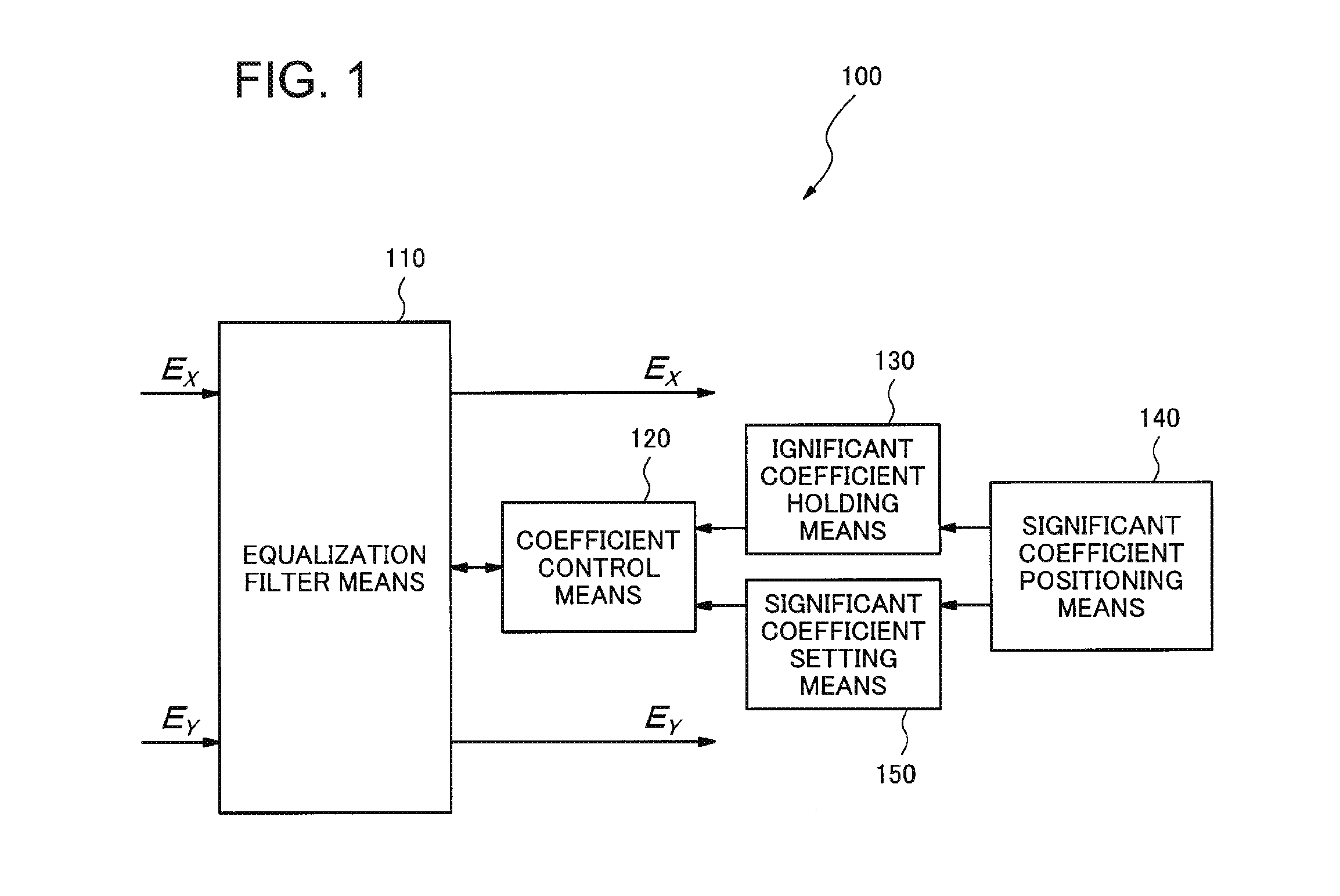
[0036]FIG. 1 is a block diagram illustrating a configuration of an equalization signal processor 100 in accordance with the first exemplary embodiment of the present invention. The equalization signal processor 100 includes an equalization filter means 110, a coefficient control means 120, a significant coefficient holding means 130, a significant coefficient positioning means 140 and a significant coefficient setting means 150.

[0037]Digital signals EX and EY received by coherent receiving systems are input into the equalization filter means 110, which outputs output signals Ex and Ey which are weighted with coefficients defining characteristics of the equalization filter means. The coefficient control means 120 controls the coefficients of the equalization filter means 110. The significant coefficient holding means 130 holds significant coefficients which are significant values among initial values of the coefficients. Here, the significant coefficient...

second exemplary embodiment

The Second Exemplary Embodiment

[0046]Next, the second exemplary embodiment of the present invention will be described. FIG. 3 is a block diagram illustrating a configuration of an equalization signal processor 200 in accordance with the second exemplary embodiment of the present invention. The equalization signal processor 200 includes the equalization filter means 110, the coefficient control means 120, the significant coefficient holding means 130, a significant coefficient positioning means 240, and the significant coefficient setting means 150. The equalization signal processor 200 differs from the equalization signal processor 100 in accordance with the first exemplary embodiment in that the significant coefficient positioning means 240 is configured to include a signal quality monitoring means 242. The signal quality monitoring means 242 detects signal quality of outputs from the equalization filter means 110, and the significant coefficient positioning means 240 determines a ...

third exemplary embodiment

The Third Exemplary Embodiment

[0066]Next, the third exemplary embodiment of the present invention will be described. FIG. 5 is a block diagram illustrating a configuration of an equalization signal processor 300 in accordance with the third exemplary embodiment of the present invention. The equalization signal processor 300 includes the equalization filter means 110, the coefficient control means 120, the significant coefficient holding means 130, a significant coefficient positioning means 340, and the significant coefficient setting means 150. The equalization signal processor 300 differs from the equalization signal processor 200 in accordance with the second exemplary embodiment in that the significant coefficient positioning means 340 is configured to include a coefficient initializing means 342 in addition to the signal quality monitoring means 242.

[0067]If the condition of the transmission line varies greatly while the coefficient control means 120 is adaptively controlling t...


PUM


Abstract

It becomes difficult to perform the optimum equalization signal processing in coherent receiving systems if a channel response in an optical fiber transmission line includes a factor without temporal centrosymmetry, therefore, an equalization signal processor according to an exemplary aspect of the invention includes an equalization filter means configured to receive digital signals by coherent receiving systems; a coefficient control means configured to control coefficients defining characteristics of the equalization filter means; a significant coefficient holding means configured to hold significant coefficients of significant values among initial values of the coefficients; a significant coefficient positioning means configured to determine a significant coefficient position, a position of the significant coefficients in the initial values, so that equalization characteristics of the equalization filter means may be optimized; and a significant coefficient setting means configured to allocate the significant coefficients to the significant coefficient position.

Description

TECHNICAL FIELD[0001]The present invention relates to equalization signal processors, optical receivers including the same, and methods for an equalization signal processing, in particular, to an equalization signal processor, an optical receiver including the same, and a method for equalization signal processing which are used in digital coherent receiving systems.BACKGROUND ART[0002]It is important in long-haul optical communications to realize high spectrum utilization efficiency and, accordingly, communication systems using multi-level modulated signals or polarization-multiplexed signals have been developed. Since coherent receiving systems can receive multi-level modulated signals and polarization-multiplexed signals, they have been used in a large number of communication systems in recent years. It is possible in the coherent receiving system to obtain the information not only on the amplitude of the received light but also on the phase of it because the received light is det...

Claims


Application Information

Patent Timeline
IPC IPC(8): H04B10/61H04B10/079
CPCH04B10/0795H04B10/6162H04B10/616
Inventor ARIKAWA, MANABUOGASAHARA, DAISAKULE TAILLANDIER DE GABORY, EMMANUELFUKUCHI, KIYOSHI
Owner NEC CORP
Learn More