Wrist Orthotic Including Adjustable Ulna Gap

a technology of wrist orthotics and ulnae, which is applied in the field of wrist orthotics, can solve the problems of limiting the adjustment range to a relatively narrow range of sizes, and achieve the effect of wide variation in forearm geometry

Active Publication Date: 2014-11-06
KILBEY BRYAN E
View PDF6 Cites 6 Cited by
  • Summary
  • Abstract
  • Description
  • Claims
  • Application Information

AI Technical Summary

Benefits of technology

[0011]A radius lace assembly is provided for adjusting the closure of the radius gap. A second adjustable closure mechanism—such as an ulna lace assembly—is preferably provided for adjusting the closure of the ulna gap when one is present. Both these adjustment features can be used to adjust the overall diameter of the brace. In addition, the radius lace assembly is secured by placing a radius tab attached to a radius lace in a desired position on the exterior of the orthotic. Varying the placement position of the radius tab varies both the width and the taper of the radius gap, so that the orthotic can accommodate wide variations in forearm geometry.

Problems solved by technology

However, these adjustments have typically been limited to a relatively narrow range of sizes.

Method used


Image

  • Wrist Orthotic Including Adjustable Ulna Gap
  • Wrist Orthotic Including Adjustable Ulna Gap
  • Wrist Orthotic Including Adjustable Ulna Gap

Examples


Embodiment Construction

[0025]The wrist splint of the present invention is preferably provided in separate right hand and left hand configurations. The two configurations are mirror images of each other. The following descriptions pertain to a right hand configuration.

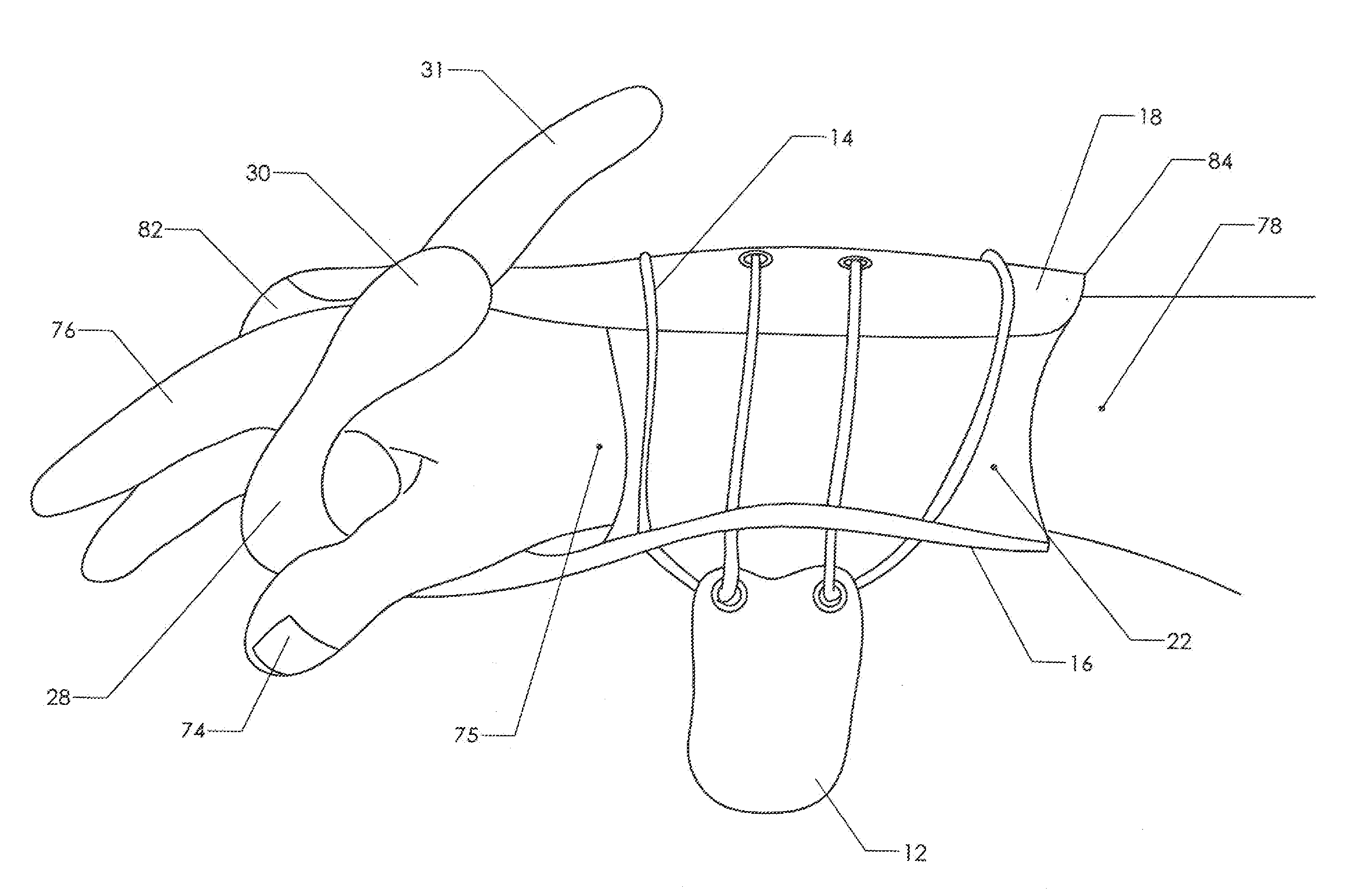
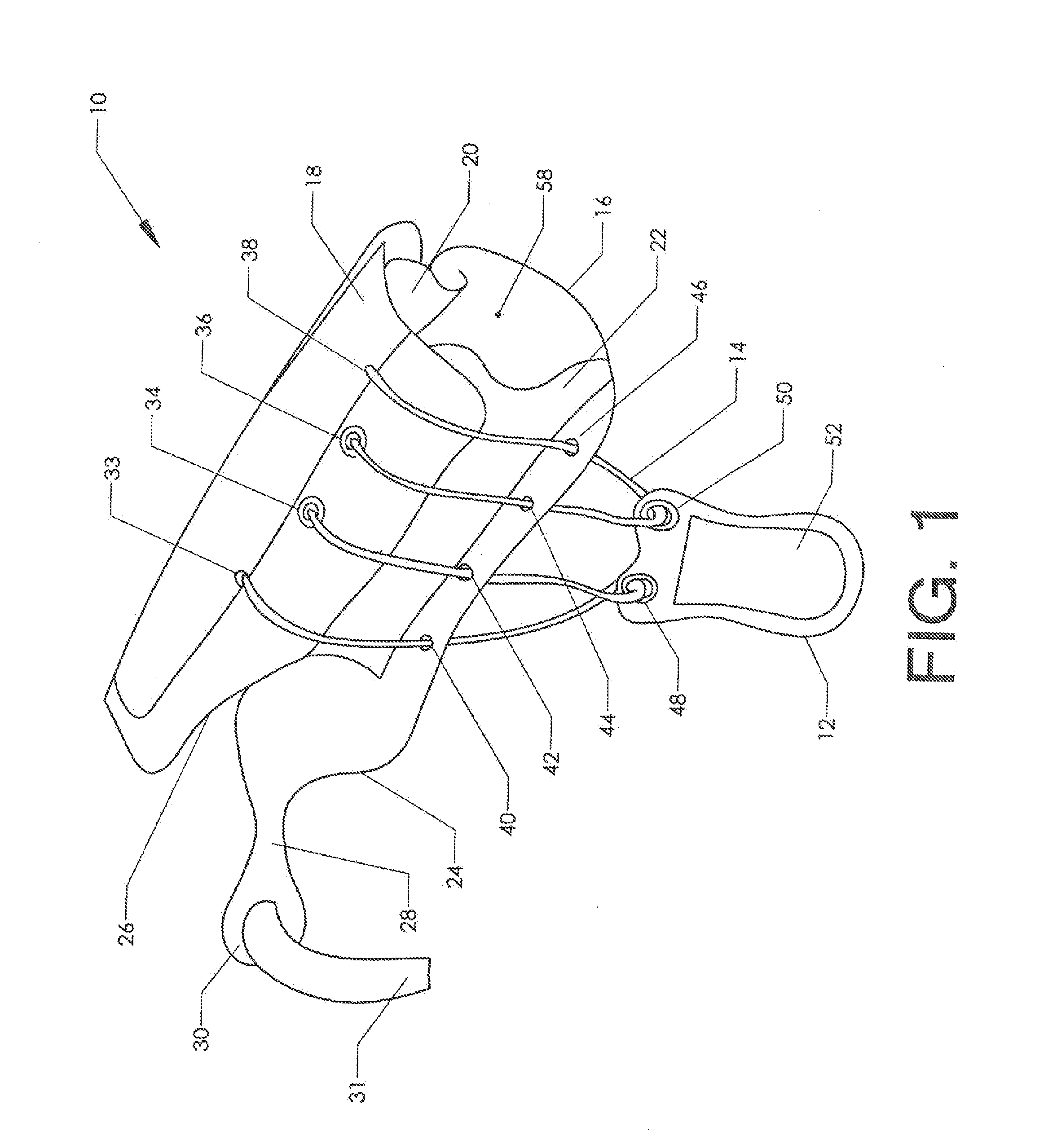
[0026]FIG. 1 shows an overall view of wrist splint 10 in an unsecured state. Top panel 18 is intended to lie over the top of the patient's forearm, wrist, and hand. Bottom panel 16 is intended to lie beneath the same anatomy.

[0027]The top and bottom panels are preferably shaped to allow at least a portion of the base of the thumb to remain outside the splint. Thus, bottom panel 16 is provided with bottom thumb relief 24 while top panel 18 is provided with top thumb relief 26. The shape of these thumb reliefs may vary according to the treatment modality. If it is desirable to largely immobilize the thumb, then the thumb reliefs will be limited in size. If on the other hand it is desirable to allow the thumb to move, then the thumb reliefs will...


PUM


Abstract

An adjustable wrist orthotic suitable for the treatment of wrist fractures and similar injuries. The orthotic preferably includes a top panel joined to a bottom panel. The top and bottom panels are preferably joined by a radius connector which spans a “radius gap” between the top and bottom panel. An “ulna gap” may optionally be provided between the top and bottom panels as well. If an ulna gap is present, then an ulna connector is preferably provided to span this gap. A radius lace assembly is provided for adjusting the closure of the radius gap. The radius lace assembly is secured by placing a radius tab attached to a radius lace in a desired position on the exterior of the orthotic. Varying the placement position of the radius tab varies the taper of the radius gap so that the orthotic can accommodate wide variations in forearm geometry.

Description

CROSS-REFERENCES TO RELATED APPLICATIONS[0001]This application is a non-provisional application claiming priority to U.S. Provisional Application No. 61 / 642,663 filed on May 4, 2012.STATEMENT REGARDING FEDERALLY SPONSORED RESEARCH OR DEVELOPMENT[0002]Not Applicable.MICROFICHE APPENDIX[0003]Not ApplicableBACKGROUND OF THE INVENTION[0004]1. Field of the Invention[0005]This invention relates to the field of medical products. More specifically, the invention comprises a wrist orthotic which may be adjusted to accommodate a wide variety of anatomical differences.[0006]2. Description of the Related Art[0007]Wrist fractures were traditionally placed in plaster casts in order to immobilize the affected anatomy. In recent years, more flexible orthotic devices have replaced plaster casts. These usually encircle the wrist and palm with fabric material. One or more rigid stays are incorporated in the device in order to provide the requisite immobilization of the joint.[0008]Elastic panels are u...

Claims


Application Information

Patent Timeline
Patent Type & Authority Applications(United States)
IPC IPC(8): A61F5/058
CPCA61F5/05866
Inventor KILBEY, BRYAN E.
Owner KILBEY BRYAN E
Why Eureka
Try Eureka