Installation structure for pedal stroke sensor

a technology of installation structure and pedal stroke sensor, which is applied in the direction of force/torque/work measurement apparatus, instruments, brake systems, etc., can solve the problems of generating friction noise, inconvenient use and poor quality, and complex structure of pedal stroke sensor, and achieves simple structure, easy reassembly of pedal stroke sensor, and easy management of pedal stroke sensor

Active Publication Date: 2014-11-13
HL MANDO CORP
View PDF18 Cites 12 Cited by
  • Summary
  • Abstract
  • Description
  • Claims
  • Application Information

AI Technical Summary

Benefits of technology

[0021]As is apparent from the above, an installation structure of a pedal stroke sensor according to an embodiment of the present disclosure has the pedal stroke sensor installed so as to be attached or detached at an outside of a brake module, thereby ensuring easy reassembly of the pedal stroke sensor.
[0022]In addition, the pedal stroke sensor is a...

Problems solved by technology

However, such a pedal stroke sensor based on angle detection, which is installed on a brake pedal spaced apart from a brake module, is subjected to a calibration for offset compensation in a state that the assembly is completed, thereby havin...

Method used


Image

  • Installation structure for pedal stroke sensor
  • Installation structure for pedal stroke sensor
  • Installation structure for pedal stroke sensor

Examples


Embodiment Construction

[0030]Reference will now be made in detail to the embodiments of the present disclosure, examples of which are illustrated in the accompanying drawings, wherein like reference numerals refer to like elements throughout.

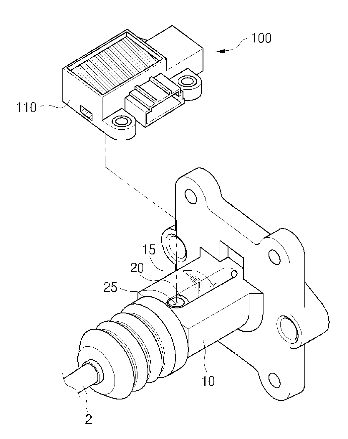
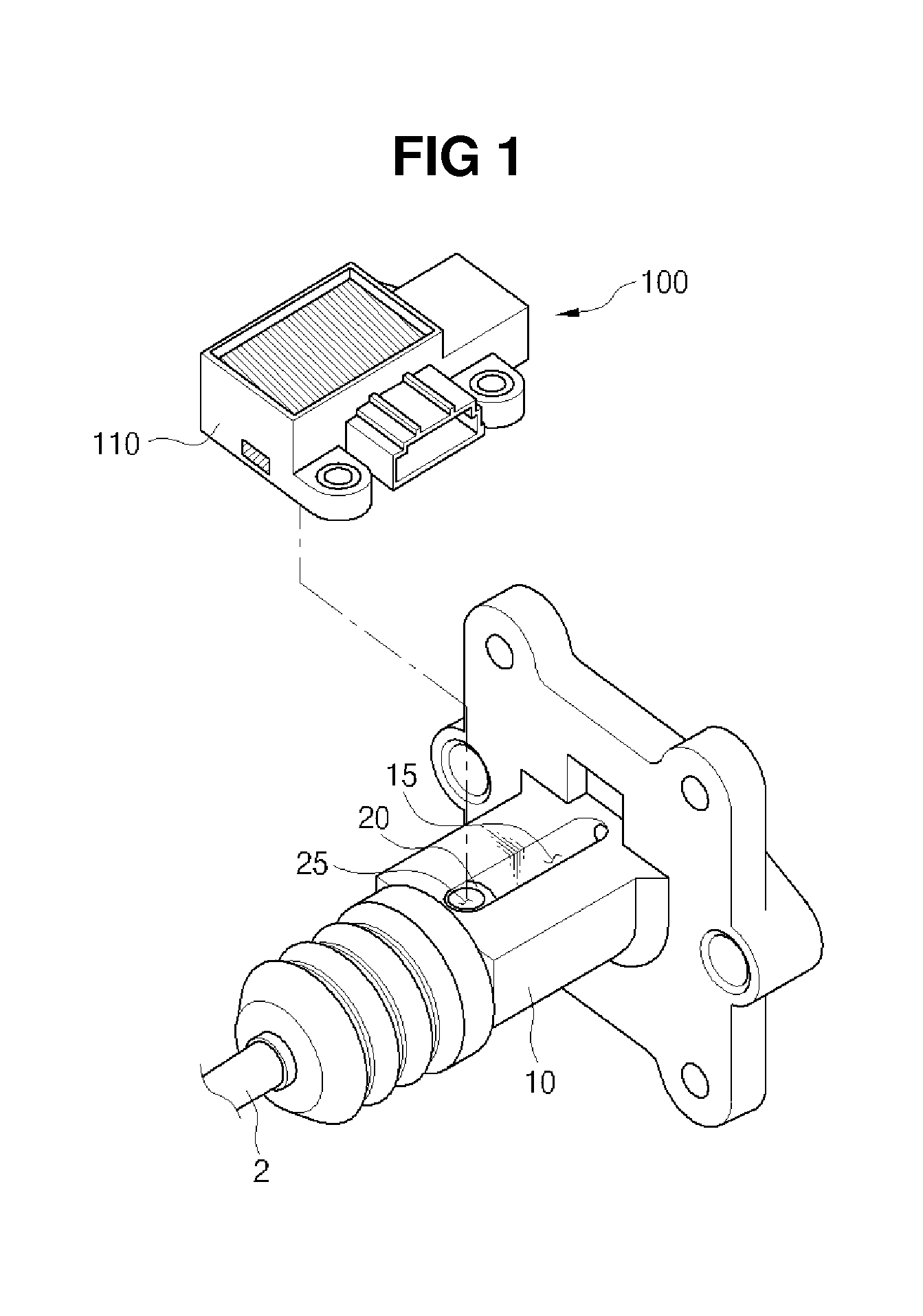
[0031]FIG. 1 is a perspective view illustrating a state of a pedal stroke sensor being installed on a housing in accordance with one embodiment of the preset disclosure.

[0032]Referring to FIG. 1, a housing 10 is provided to allow a moving member 20, which interworks according to a stepping force of a brake pedal (not shown), to be slid thereinto. In this case, the moving member 20 may be implemented using a control plunger connected to an input shaft 2 that moves in a horizontal direction by a stepping force of a brake pedal. Such a moving member 20, which is coupled to a sensor for sensing a displacement, may be used may be coupled to any device for sensing a stroke and used.

[0033]The housing 10 is provided at an outer surface thereof with a mounting surface on which...


PUM


Abstract

Disclosed is an installation structure of a pedal stroke sensor configured to measure a displacement of a moving member interworking according to a stepping force of a brake pedal. The pedal stroke sensor provided with a sensing member to sense a change in displacement according to movement of the moving member in a non-contact manner is installed at an outside of a housing that allows the moving member to be slid thereinto, the sensing member is provided with a sensor housing that is detachably installed at the outside of the housing, a hall IC (integrated circuit) provided in the sensor housing to sense change in magnetic force, and a magnet housing provided in the sensor housing so as to move while facing the hall IC and on which a magnet is installed, and an elongated hole is formed through an outer surface of the housing in a direction in which the moving member moves, and the moving member is connected to the magnet housing by using a connecting member such that the moving member moves together with the magnet housing through the elongated hole.

Description

CROSS-REFERENCE TO RELATED APPLICATION[0001]This application claims the benefit of Korean Patent Application No. 2013-0053549, filed on May 13, 2013 in the Korean Intellectual Property Office, the disclosure of which is incorporated herein by reference.BACKGROUND[0002]1. Field[0003]Embodiments of the present disclosure relate to an installation structure of a pedal stroke sensor, and more particularly, to an installation structure of a pedal stroke sensor ensuring easy assembly while simplifying a structure of the pedal stroke sensor.[0004]2. Description of the Related Art[0005]In general, a vehicle has a mechanism configured to detect a rotating angle of a pedal arm of a brake pedal or an accelerator pedal at all times, and based on the detected data, perform a precise control.[0006]For example, a rotating angle of a pedal arm of a brake pedal is detected using a pedal stroke sensor to control a device in an electronic manner. Such a pedal stroke sensor is disclosed in Korean Paten...

Claims


Application Information

Patent Timeline
IPC IPC(8): G01L5/28B60T7/06
CPCG01L5/28B60T7/06B60T2220/04B60T7/042B60K26/02B60T8/88B60T13/66G01L5/225
Inventor SIM, GYUNG-HUN
Owner HL MANDO CORP
Why Eureka
Try Eureka