Roll Coolant Valve for Rolling

a technology of coolant valve and rolling valve, which is applied in the direction of valve operating means/release devices, mechanical equipment, manufacturing tools, etc., can solve the problem of not providing a valve type that is normally open, and achieve the effect of suitably adjusting the strength of the magnetic for

Inactive Publication Date: 2014-11-13
TOYONAGA SHOICHI +2
View PDF4 Cites 3 Cited by
  • Summary
  • Abstract
  • Description
  • Claims
  • Application Information

AI Technical Summary

Benefits of technology

[0018]In the present invention, the term “roll coolant valve” means a valve that controls ON / OFF of the jet of the coolant to the work roll during a rolling process. The coil can be made from any material that can generate magnetic force when energized. The strength of its magnetic force can be suitably adjusted.

Problems solved by technology

However, because many changes are necessary, a valve of a type that is normally open has not been provided.

Method used


Image

  • Roll Coolant Valve for Rolling
  • Roll Coolant Valve for Rolling
  • Roll Coolant Valve for Rolling

Examples


Embodiment Construction

[0028]The roll coolant valve of the present invention is explained in detail below.

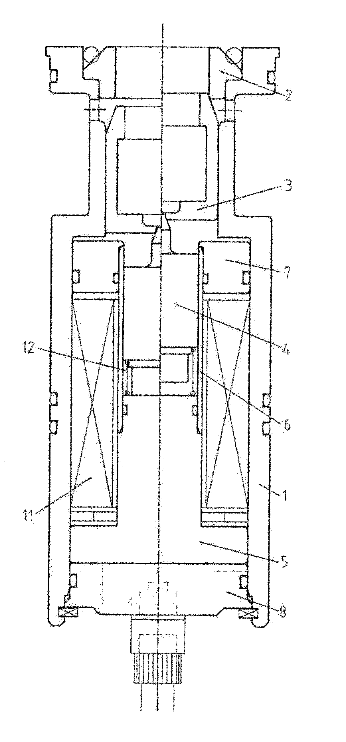
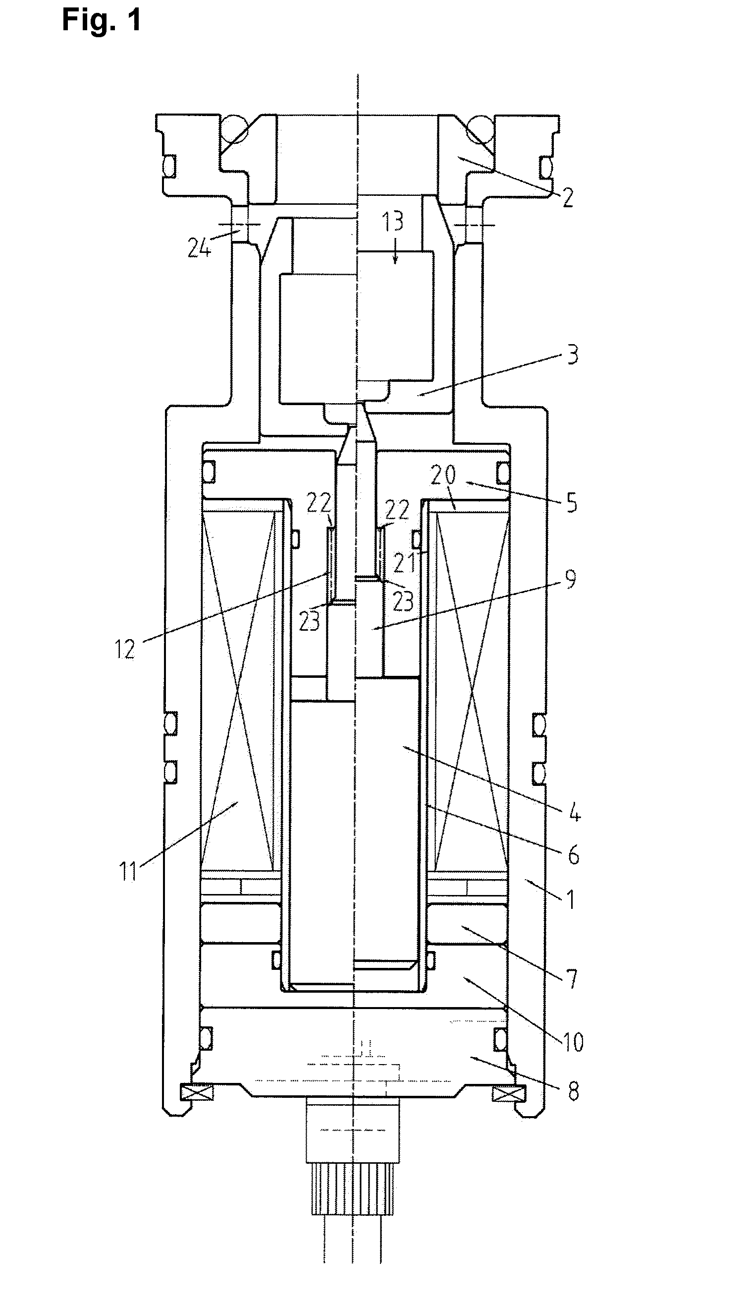
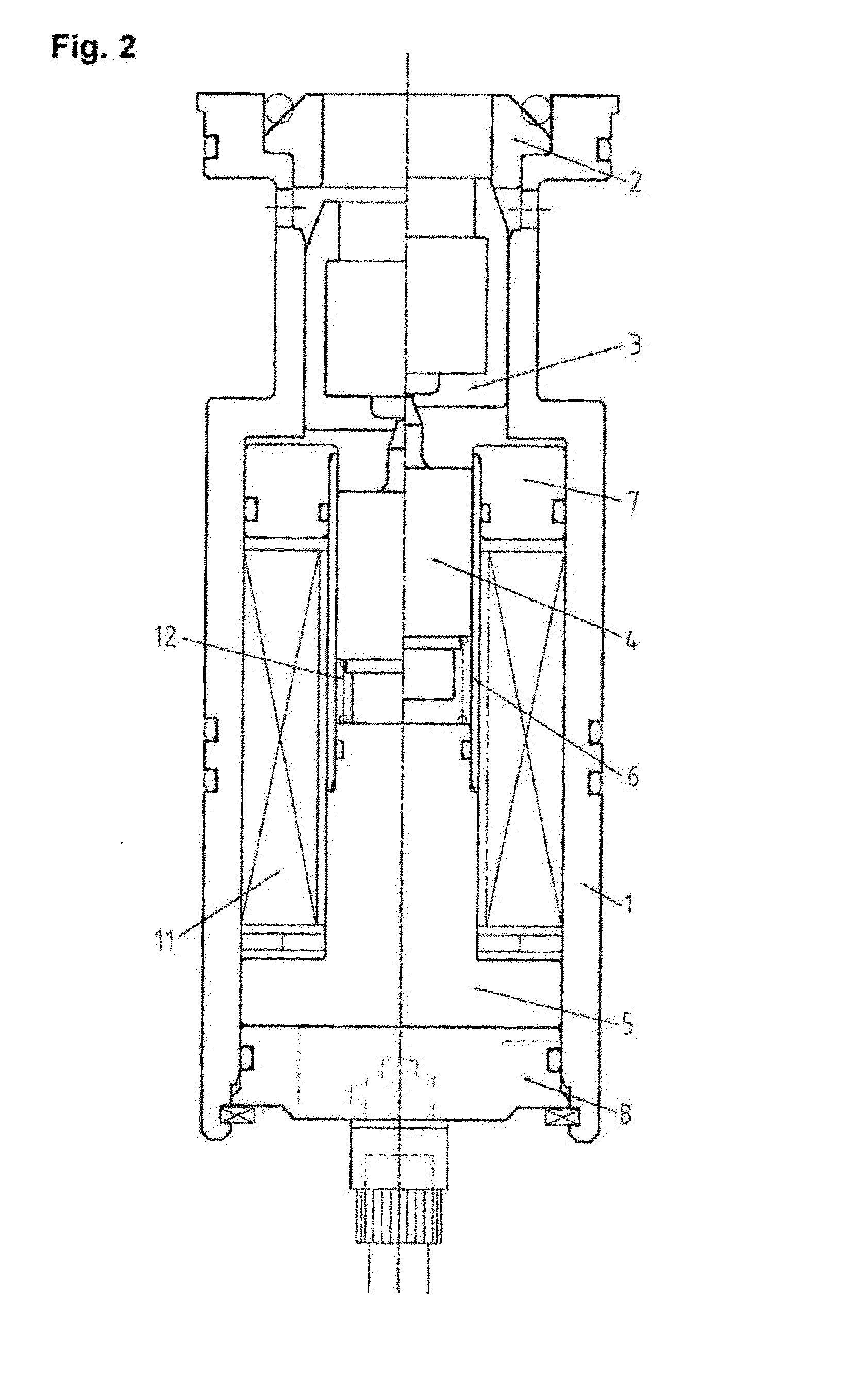
[0029]The coolant valve of the present invention shown in FIG. 1 comprises a valve body 1, an end cover 8, a coil 11, a needle 9, a fixed core 5, a movable core 4, a poppet 3, a spring 12 and a power supply circuit (not shown in the figure). End cover 8 is set in an end of valve body 1 so that a cavity having an opening is formed. The opening works as a discharging opening 13 for coolant from the valve. In the specification of the present application, a direction toward the discharging opening is referred to as forward, and a direction toward the end cover is referred to as backward. A direction that connects the end cover and the discharging opening is referred to as longitudinal.

[0030]Coil 11 is an annular hollow coil arranged along the inner sidewall of the valve body. The fixed core has a shape, which is a combination of an annular hollow basic disk and a hollow cylindrical portion extending from ...


PUM

PropertyMeasurementUnit
poweraaaaaaaaaa
poweraaaaaaaaaa
voltageaaaaaaaaaa

Abstract

The invention of the present application addresses the problem of providing a normally open roll coolant valve. This roll coolant valve includes: a valve body (1); an end cover (8) fitted into one end of the valve body (1); an annular coil (11) provided along the inside wall of the valve body (1); a stationary core (5) having a form whereby a hollow disc-shaped base part and a hollow annular part extending therefrom are formed integrally, and arranged so as to make contact with the coil (11); a needle (9) that is capable of sliding within the aforementioned hollow annular part and making contact with the rear aperture of a poppet (3) to seal this aperture; a movable core (4) that has the needle (9) and is arranged so as to be capable of sliding on the inner surface of the coil (11); an elastic element (12) provided between the stationary core (5) and the movable core (4); and a circuit for supplying power to the aforementioned coil.

Description

TECHNICAL FIELD OF THE INVENTION[0001]The present invention relates to a roll coolant for rolling.BACKGROUND[0002]In a rolling process, a coolant such as kerosene, emulsion of oil and water, or water is jetted to a work roll for controlling local expansion of a rolling material and local shape distortions. The plural spray nozzles which jet the coolant are arranged along the width of the work roll of the rolling material, and the coolant is jetted from the spray nozzle to the work roll. The coolant jet is ON / OFF controlled independently in each spray nozzle.[0003]By the ON / OFF control of a coolant jet, a jetted part of the work roll is cooled and contracted and, on the other hand, a non jetted part of the work roll expands due to a heat during rolling. Therefore, in the expanded part of the work roll, the rolling material becomes thinner. In the contracted part of the work roll, an elongation of the rolling material is restrained. In other words, the part of the rolling material tha...

Claims


Application Information

Patent Timeline
Patent Type & Authority Applications(United States)
IPC IPC(8): B21B27/10F16K31/06
CPCB21B27/10F16K31/0658B21B2027/103B21B45/0233F16K31/0655F16K31/0675
Inventor TOYONAGA, SHOICHIAKAYA, KOJINAKAZATO, YOSHIHITO
Owner TOYONAGA SHOICHI
Why Eureka
Try Eureka