
Image adjusting method, light source module and electronic device

a technology of light source module and image adjusting method, which is applied in the direction of instruments, computing, electric digital data processing, etc., can solve the problems of lower luminous efficacy of light source of wide gamut display device, shorter product life, and higher power consumption of products, so as to prolong the product life and high quality images

Active Publication Date: 2014-11-13
HTC CORP
View PDF4 Cites 1 Cited by
  • Summary
  • Abstract
  • Description
  • Claims
  • Application Information

AI Technical Summary

Benefits of technology

The invention provides an image adjusting method that can display high quality images and prolong the lifetime of products. It uses a light source module with high color saturation, high luminous efficacy, and long lifetime. The electronic device also has high color saturation and long lifetime. These features can satisfy the wide gamut requirements of some images and increase luminous efficacy.

Problems solved by technology

However, comparing with a light source that adopts blue light LED chips accompanying with Yttrium Aluminum Garnet (YAG), luminous efficacy of the light source of the wide gamut display device is lower, such that products have higher power consumption and shorter product lifetime.

Method used


Image

  • Image adjusting method, light source module and electronic device
  • Image adjusting method, light source module and electronic device
  • Image adjusting method, light source module and electronic device

Examples


Embodiment Construction

[0027]Reference will now be made in detail to the present preferred embodiments of the invention, examples of which are illustrated in the accompanying drawings. Wherever possible, the same reference numbers are used in the drawings and the description to refer to the same or like parts.

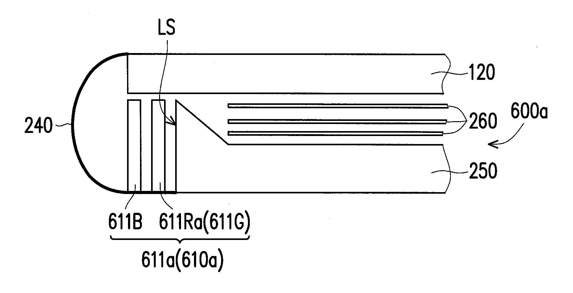
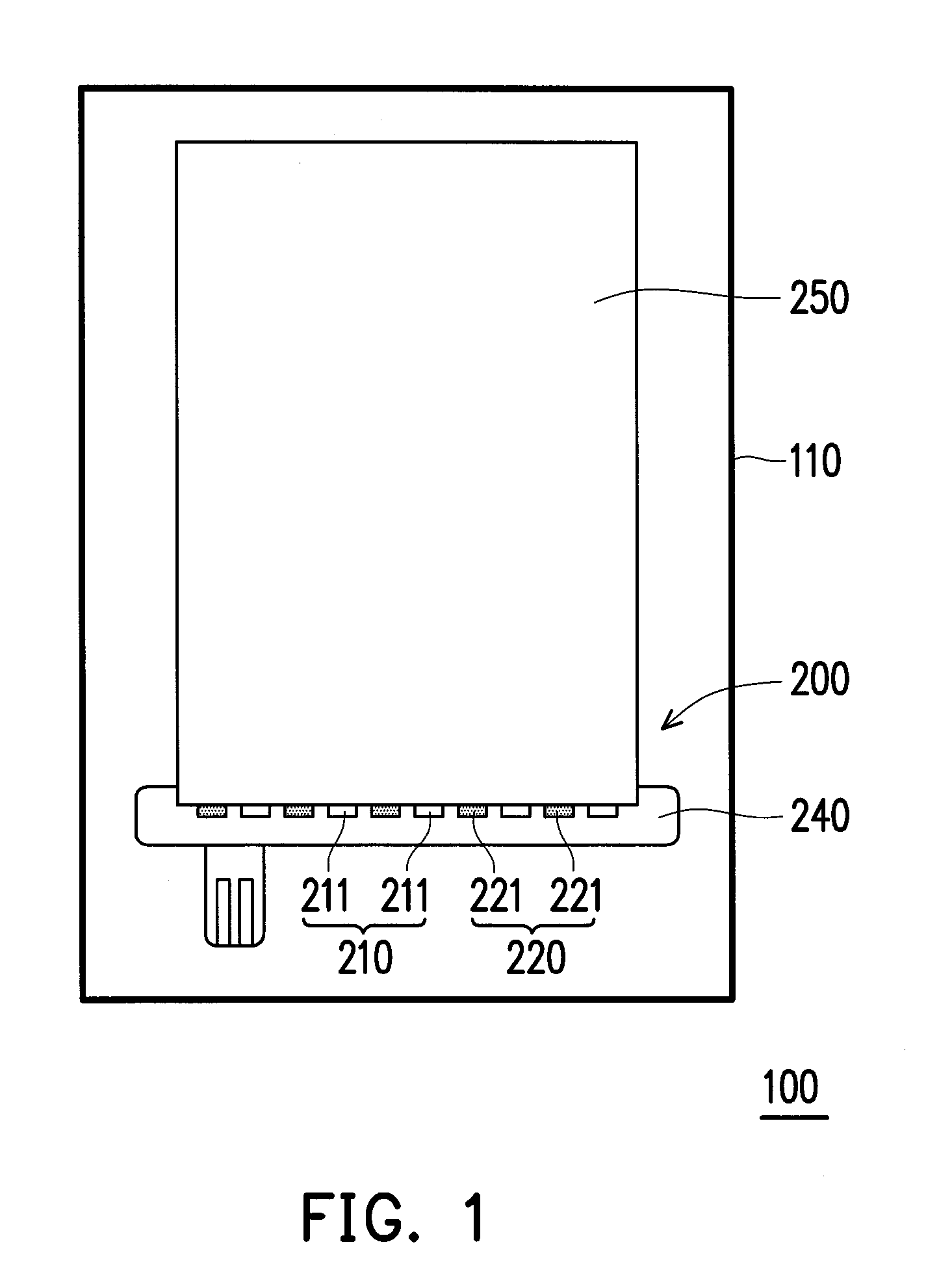
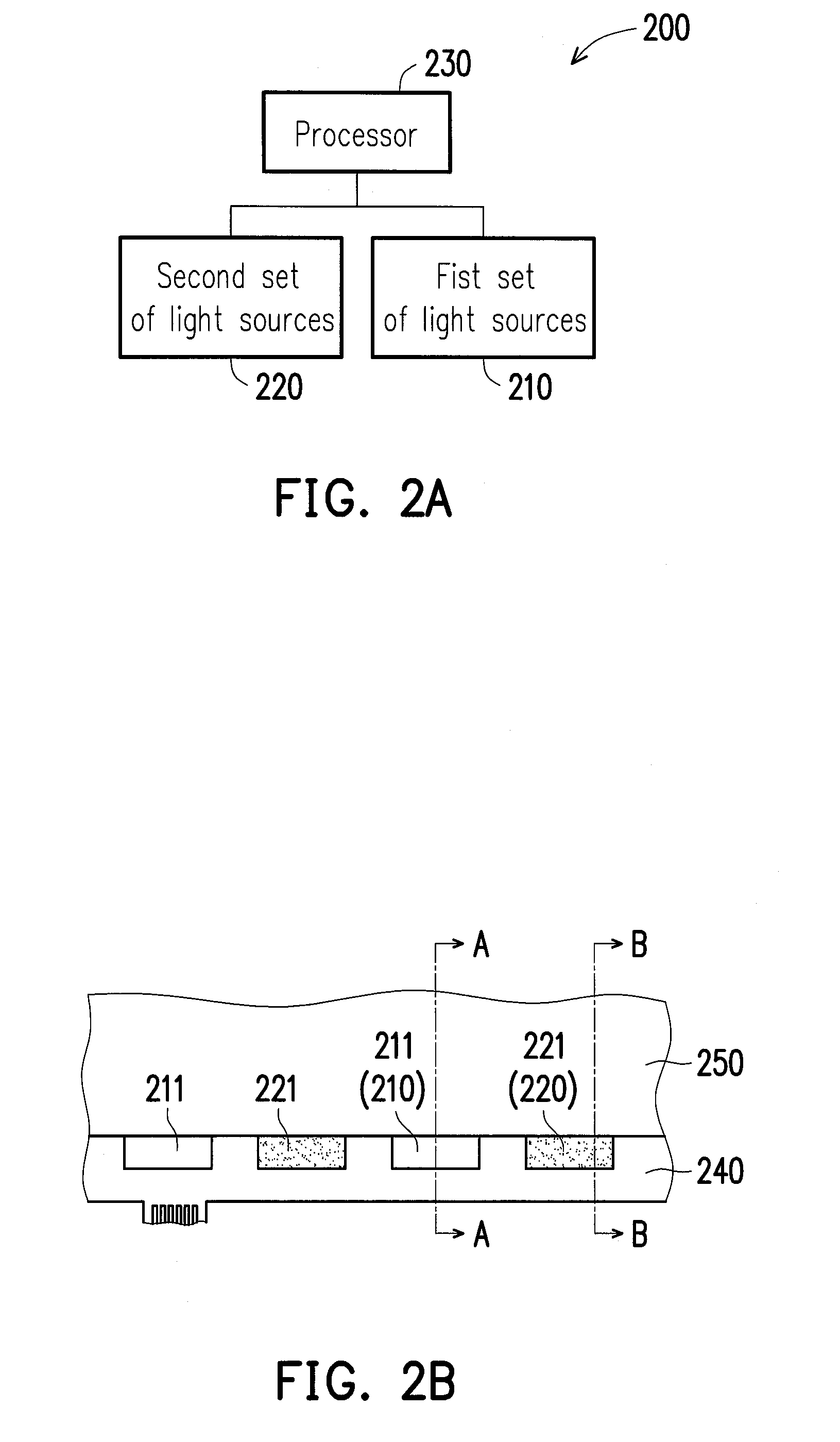
[0028]FIG. 1 is an architecture diagram of an electronic device of an embodiment of the invention. FIG. 2A is a block diagram of the light source module of FIG. 1. FIG. 2B is an architecture diagram of the light source module of FIG. 1. Please referring to FIG. 1, an electronic device 100 includes a body 110 and a light source module 200. As shown in FIG. 2A, the light source module 200 is disposed in the body 110 in the embodiment. The light source module 200 includes a first set of light sources 210, a second set of light sources 220, and a processor 230, wherein the gamut of the first set of light sources 210 is wider than that of the second set of light sources 220, and luminous efficacy of the s...


PUM


Abstract

An image adjusting method, a light source module, and an electronic device are provided. The image adjusting method includes the following steps. A first set of light source and a second set of light source of the light source module are driven independently by corresponding driving intensity respectively. An image display command is received. The driving intensity corresponding to the first set of light sources and the second set of light sources respectively are adjusted according to the image display command, wherein a gamut of the first set of light sources is wider than that of the second set of light sources, and luminous efficacy of the second set of light sources is higher than that of the first set of light sources.

Description

CROSS-REFERENCE TO RELATED APPLICATION[0001]This application is a continuation-in-part application of and claims the priority benefit of a prior application Ser. No. 13 / 890,262, filed on May 9, 2013, now pending. The entirety of the above-mentioned patent application is hereby incorporated by reference herein and made a part of this specification.BACKGROUND OF THE INVENTION[0002]1. Field of the Invention[0003]The invention generally relates to an image adjusting method, a light source module, and an electronic device, in particular, to an image adjusting method, a light source module, and an electronic device that may adjust luminance intensity of a light source.[0004]2. Description of Related Art[0005]Because liquid crystal display (LCD) devices go toward the development trend of high color saturation gradually in recent years, the product research of a wide gamut display device has been emphasized by those of the related domain. In general speaking, a light source of the wide gamu...

Claims


Application Information

Patent Timeline
Patent Type & Authority Applications(United States)
IPC IPC(8): G09G5/10
CPCG09G5/10G09G3/3406G09G2320/0606G09G2320/0626G09G2320/0666
Inventor FAN, FU-CHENG
Owner HTC CORP
Learn More