Self-power circuit for protecting relay

a self-power circuit and relay technology, applied in the field of relay protection, can solve the problems of large capacity of semiconductor switch b>42/b>, damage to the mcu b>50/b>, etc., and achieve the effect of stable operation

Inactive Publication Date: 2014-11-13
LSIS CO LTD
View PDF6 Cites 10 Cited by
  • Summary
  • Abstract
  • Description
  • Claims
  • Application Information

AI Technical Summary

Benefits of technology

[0032]Therefore, an aspect of the present disclosure is to provide a self-power circuit for a protecting relay capable of being s

Problems solved by technology

Thus, if a current having larger than tens of amperes flows to the first resistor R1, the first resistor R1 may be damaged to

Method used


Image

  • Self-power circuit for protecting relay
  • Self-power circuit for protecting relay
  • Self-power circuit for protecting relay

Examples


Embodiment Construction

[0053]Description will now be given in detail of the exemplary embodiments, with reference to the accompanying drawings. For the sake of brief description with reference to the drawings, the same or equivalent components will be provided with the same reference numbers, and description thereof will not be repeated.

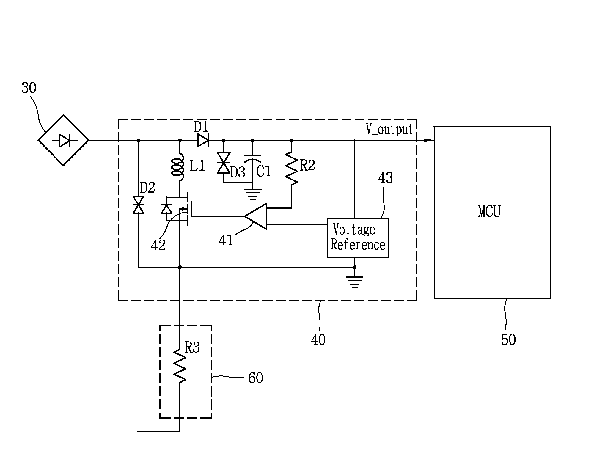
[0054]A self-power circuit for a protecting relay according to an exemplary embodiment of the present disclosure will be described with reference to FIG. 3 as a block diagram illustrating a configuration of the self-power circuit.

[0055]The self-power circuit for a protecting relay according to an exemplary embodiment of the present disclosure includes a rectifying circuit section 30 and a power source circuit section 40.

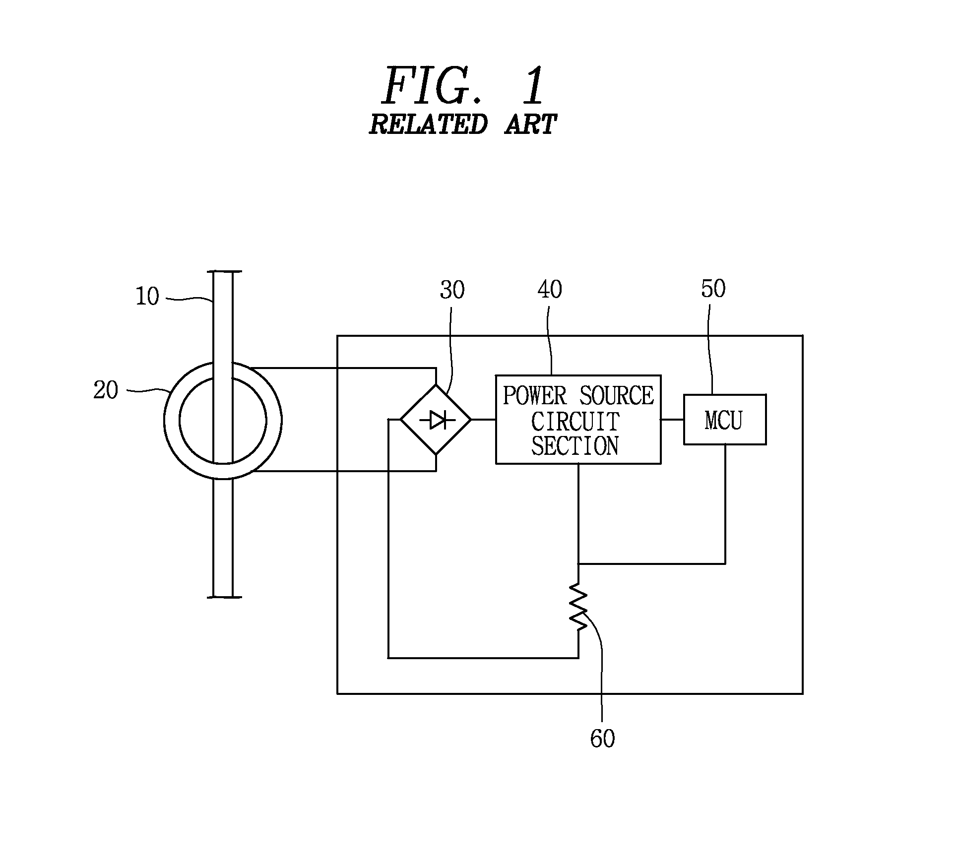
[0056]In FIG. 3, a current transformer (please refer to reference numeral 20 of FIG. 1) installed in a power line (please refer to reference numeral 10 of FIG. 1) of an electric power system to detect an amount of current flowing through the power line and ...


PUM


Abstract

A self-power circuit for a protecting relay includes: a rectifying circuit section rectifying an AC current from an electric power system; a power source circuit section includes: a comparator comparing whether an output voltage from the rectifying circuit section exceeds a reference voltage and a semiconductor switch configured to be switched by an output from the comparator, and supply the output voltage from the rectifying circuit section, as a constant voltage to a microcomputer unit of the protecting relay; an inductor configured to, when a DC current supplied from the rectifying circuit section is rapidly increased, gradually increase the DC current to flow to thus have an increased voltage thereacross; and a bi-directional diode connected between the power source circuit section and a ground and turned on to form a bypass path of a current when a DC voltage supplied from the power source circuit section is rapidly increased.

Description

CROSS-REFERENCE TO RELATED APPLICATION[0001]Pursuant to 35 U.S.C. §119(a), this application claims the benefit of earlier filing date and right of priority to Korean Application No. 10-2013-0053838, filed on May 13, 2013, the contents of which is incorporated by reference herein in its entirety.BACKGROUND OF THE INVENTION[0002]1. Field of the Invention[0003]The present disclosure relates to a protecting relay, and particularly, to a self-power circuit for a protecting relay directly delivering electric power source from an electric power system as a monitoring target.[0004]2. Background of the Invention[0005]In an electric power system, a circuit breaker or a switchgear is used to separate a section or isolate a fault current, and such a circuit breaker or a switchgear includes a protecting relay as a controller for performing electrical controlling such as detection of a fault current and controlling circuit breaking, for example.[0006]In general, a protecting relay has a Direct Cu...

Claims


Application Information

Patent Timeline
IPC IPC(8): H02H9/04
CPCH02H9/04H02H1/06H02H9/041H02H1/04H02H9/02
Inventor AHN, HONG SEON
Owner LSIS CO LTD
Why Eureka
Try Eureka