Wind turbine blade control method

a control method and wind turbine technology, applied in the direction of engine control, motors, propellers, etc., to achieve the effect of reducing the modal vibration of the blad

Active Publication Date: 2014-11-13
LM WP PATENT HLDG
View PDF4 Cites 14 Cited by
  • Summary
  • Abstract
  • Description
  • Claims
  • Application Information

AI Technical Summary

Benefits of technology

[0007]adjusting at least one active lift device provided on said blade to reduce a modal vibration of said bl

Problems solved by technology

It is a continued challenge to design blades for wind turbines having such AADs in location

Method used


Image

  • Wind turbine blade control method
  • Wind turbine blade control method
  • Wind turbine blade control method

Examples


Embodiment Construction

[0072]An embodiment of the invention will now be described, by way of example only, with reference to the accompanying drawings, in which:

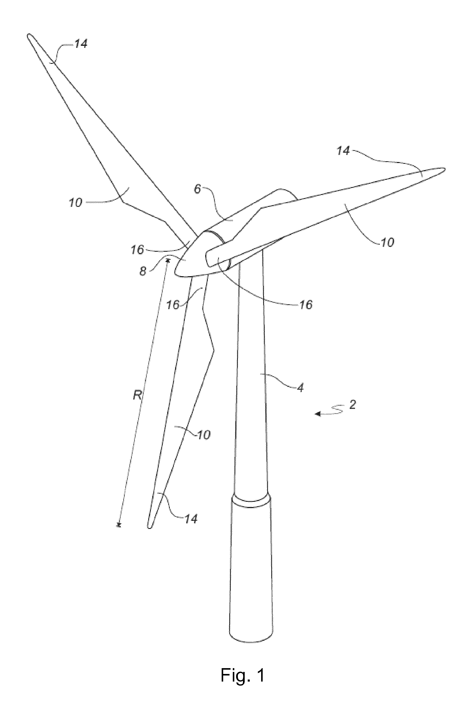
[0073]FIG. 1 shows a wind turbine;

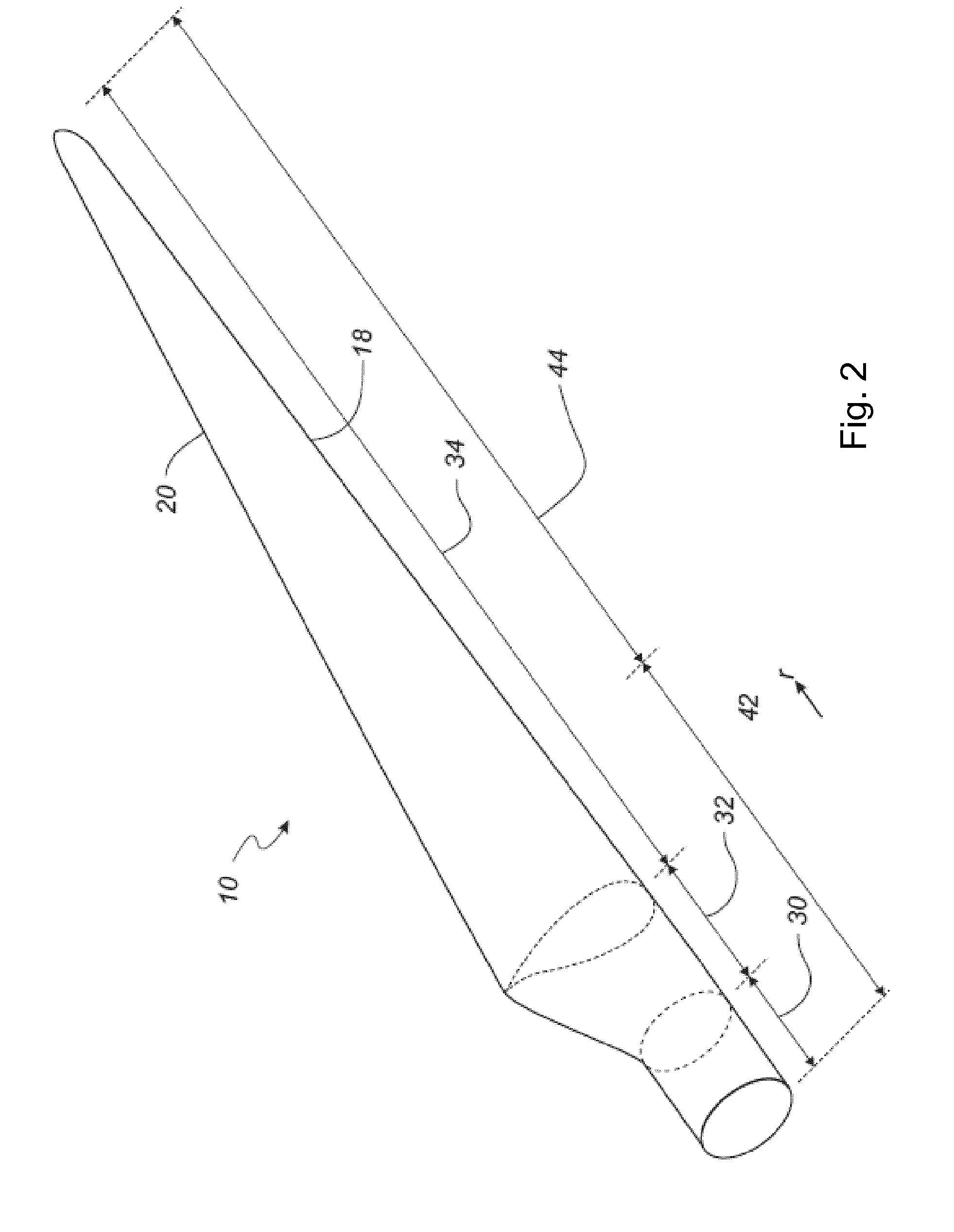
[0074]FIG. 2 shows a schematic view of a wind turbine blade according to the invention;

[0075]FIG. 3 shows a schematic view of an airfoil profile of the blade of FIG. 2;

[0076]FIG. 4 is an illustrative view of a wind turbine blade having an Active Aerodynamic or Active Lift Device;

[0077]FIG. 5 is an illustration of the coordinate system used;

[0078]FIG. 6 is a plot of the dominant mode shapes in a wind turbine blade;

[0079]FIG. 7 is a series of plots of the step response to a flap deflection, showing bending moments and mode shape coordinates;

[0080]FIG. 8 is a plot of the controllability of different blade modes for different locations of AADs;

[0081]FIG. 9 is a series of plots of the controllability between mode 1 and mode 2 of the blade;

[0082]FIG. 10 is a plot of the controllability Gramian HSV corresponding to mode ...


PUM


Abstract

A control method for a wind turbine, in particular for a wind turbine blade is described. The control method makes use of the blade mode shapes, or natural vibration shapes, of the blade to detect the excitement level of the blade natural vibrations, and controls active lift devices on the blade in an effort to reduce the excitement levels, to reduce loading in the blade and the overall wind turbine structure. There is also provided a method of designing a wind turbine blade for use in such a method.

Description

FIELD OF THE INVENTION[0001]The present invention relates to a control method for a wind turbine blade, and a method of designing a wind turbine blade, and a wind turbine blade designed according to the method.BACKGROUND OF THE INVENTION[0002]Active aerodynamic devices are currently being investigated for use in wind turbine blades in order to decrease the time varying loads on the structure. Active aerodynamic devices (AAD) is the broad term for devices which can manipulate the aerodynamics of the blade sections in a variable and controllable manner. An example of an active aerodynamic device is the trailing edge flap, which is very similar to the outboard aileron of an airplane wing. By mounting such devices on the blades and appropriate control, the loads which are induced by turbulence can partly be cancelled out.[0003]It is a continued challenge to design blades for wind turbines having such AADs in locations to provide maximum performance, as well as an appropriate method of c...

Claims


Application Information

Patent Timeline
IPC IPC(8): F03D7/02F03D7/04
CPCF03D7/0232F03D7/045F03D7/0296F03D7/043F05B2240/31F05B2270/334Y02E10/72Y02P70/50
Inventor BAEK, PETERANDERSEN, CHRISTIAN FRANKSLOT, MARK OLAFSKOVBY, CASPERBOJESEN, SIMON BERGRAVN, MORTENKLITGAARD, MICHAEL
Owner LM WP PATENT HLDG
Why Eureka
Try Eureka