Programmable Electronic Card and Supporting Device

a technology of supporting device and electronic card, which is applied in the field of programmable electronic card and supporting device, can solve the problems of not being popular in most phones and pos terminals, not being able to handle 'swiping' of smart phones, and being difficult to force consumers to change their behavior

Inactive Publication Date: 2014-11-20
TNT PARTNERS
View PDF10 Cites 247 Cited by
  • Summary
  • Abstract
  • Description
  • Claims
  • Application Information

AI Technical Summary

Benefits of technology

[0008]A programmable electronic card is disclosed having, among other things, a dynamic reprogrammable magnetic stripe, dynamic programmable EMV chip, programmable NFC chip, Bluetooth technology, programmable RF chip, wireless transmitter, GPS, ultra-thin battery, and flexible displays (e.g., OLED screen, eInk screen, etc.). The electronic card is configured to provide credit card, electronic wallet, digital identification functionalities, among many other functionalities. The components of the electronic card are configured to fit within the size of a ISO / IEC 7810 ID-1 plastic card and function as a smart electronic device. A display screen (e.g., graphical user interface screen) allows a user to select one of the plurality of card accounts for use and displays a graphical emulation of a physical card on the user interface screen corresponding to the selected card account. Selecting a card account electronically reprograms the magnetic stripe, and / or EMV, and / or NFC chip to include information relating to the selected credit card for subsequent use of the card at a point of sale.

Problems solved by technology

Currently, the mobile wallet is primarily designed to work on NFC technology as the phone itself is not able to carry the credit card specific communication methods of a magnetic stripe or an EMV chip.
However, POS readers are not formatted to handle ‘swiping’ of the smart phones due to the thickness of the phones.
However, at this time, NFC is not popular in most phones and POS terminals.
Moreover, NFC requires a user to use ‘tap’ action rather than ‘swipe’ action, which is very different, although arguably equally convenient, making it hard to force consumers to change their behavior from ‘swiping.’ A mobile wallet application on a phone also takes time-consuming actions to make a purchase, such as the following high-level examples: unlocking the phone, selecting an application, and then selecting a payment method.
The combination of all of these factors has made the commercialization of smart phone-based mobile wallets very challenging.

Method used


Image

  • Programmable Electronic Card and Supporting Device
  • Programmable Electronic Card and Supporting Device
  • Programmable Electronic Card and Supporting Device

Examples


Embodiment Construction

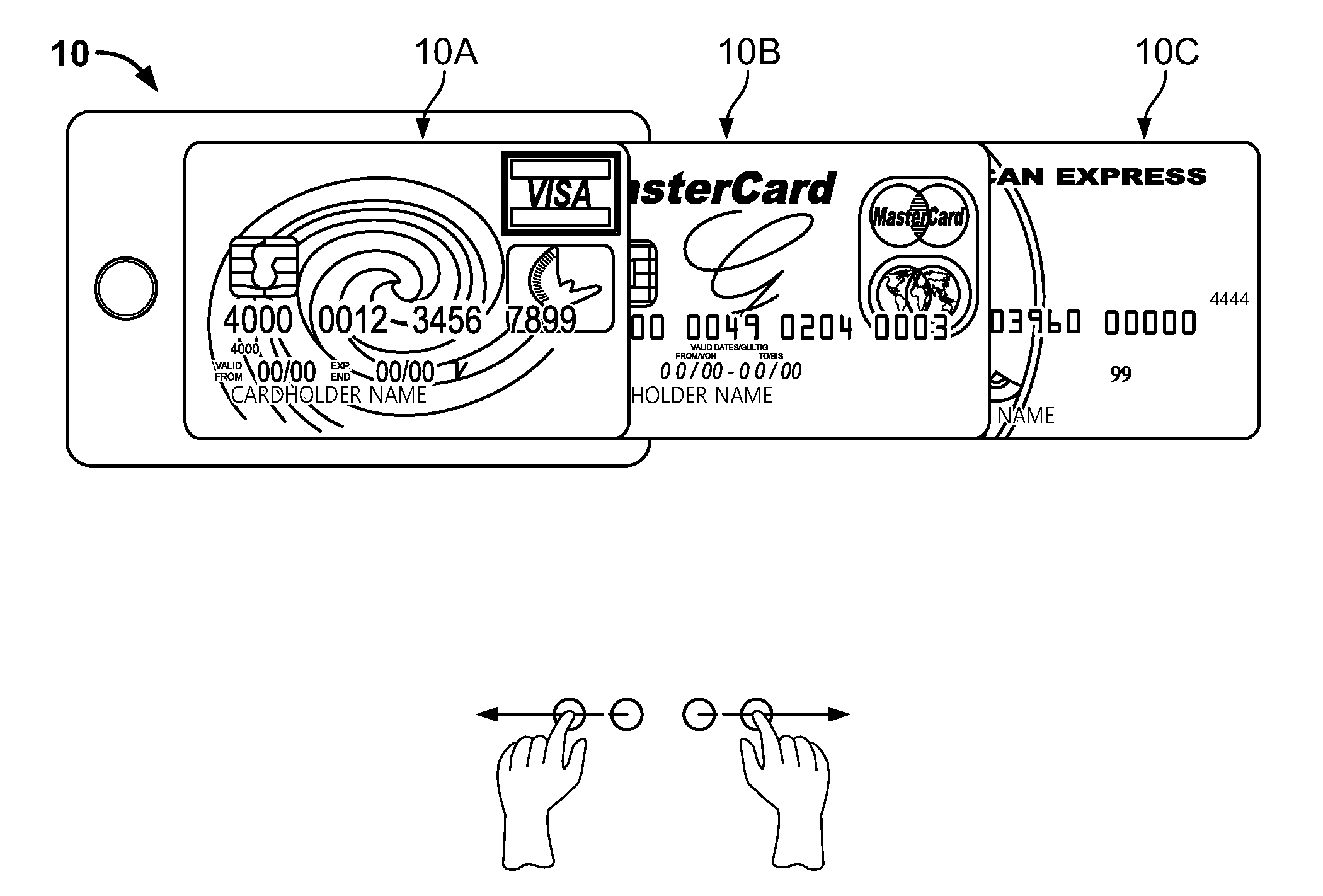
[0036]A programmable electronic card (e.g., electronic credit card), as discussed herein, functions as a smart electronic wallet on a credit card sized device having a display screen (e.g., electronic ink (eInk) screen, flexible organic light emitting diode (OLED) screen, etc.) providing touch-friendly behaviors, text inputs via virtual keyboards, scrolls, etc. The electronic card is battery powered. The basic components of the electronic card (e.g., front, back, internal, etc.) are described below with reference to FIGS. 1-18.

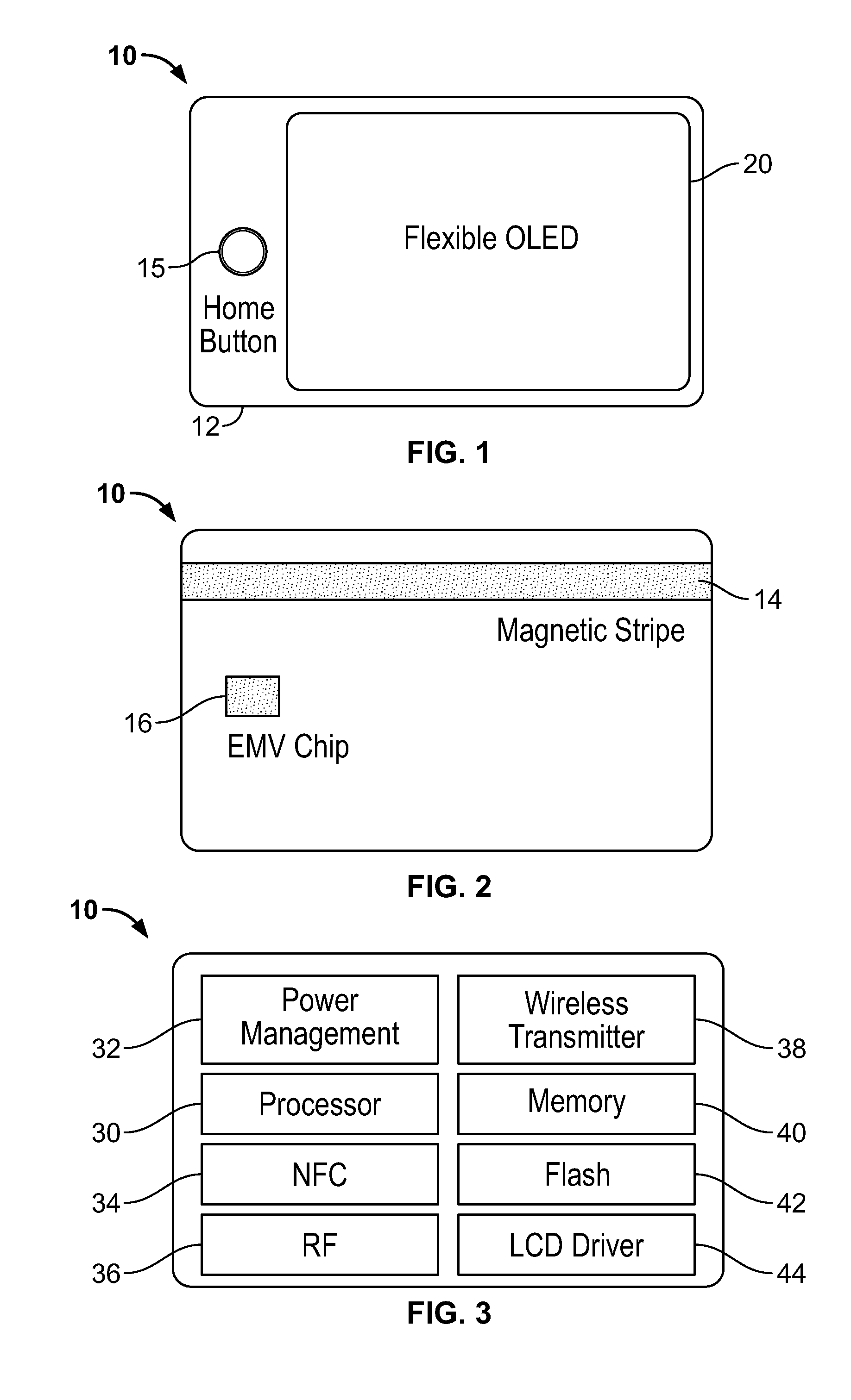
[0037]FIG. 1 shows a front view of the electronic card, generally indicated at 10, comprising a body 12, a home button 15 (which could include fingerprint scanning functionality), and a display 20. The display 20 comprises a graphical user interface screen positioned in a front surface of the card body. The display 20 could be an OLED display, or other display, and could be flexible or bendable. The display 20 could include a touch screen, which could have a h...


PUM


Abstract

A programmable electronic card assembly is provided. The programmable electronic card assembly comprising a smart phone having a receptacle, and a programmable electronic card positionable within and removable from the receptacle of the smart phone for providing power and communications interfaces with the electronic card, the card including a card body and a reprogrammable magnetic stripe positioned on a surface of the card body.

Description

CROSS-REFERENCE TO RELATED APPLICATION[0001]This application is a continuation-in-part of U.S. patent application Ser. No. 14 / 243,099 filed Apr. 2, 2014, which claims priority to U.S. Provisional Patent Application No. 61 / 807,720 filed on Apr. 2, 2013, the disclosures of which are incorporated herein in their entirety by reference and made a part hereof.BACKGROUND OF THE INVENTION[0002]1. Field Of The Invention[0003]The present invention relates to a programmable electronic card and supporting device.[0004]2. Related Art[0005]Credit cards are conventionally made of plastic, usually flexible, in the format of ISO / IEC 7810 ID-1 and contain a magnetic stripe (e.g., magstripe). Such cards can also include an EMV (Europay, MasterCard and Visa) chip and an NFC (Near Field Communication) chip with unique account information. These components contain a unique number for a stored value account or an individual identification number. This particular card format has expanded in use to include ...

Claims


Application Information

Patent Timeline
Patent Type & Authority Applications(United States)
IPC IPC(8): G06K19/06H02J7/00G06F1/16
CPCG06K19/06206H02J7/0044G06F1/1628G06K19/07354G06K19/07707G06Q20/3227G06Q20/3415G06Q20/353G07F7/0846G07F7/0853G07F7/0873G07F7/0893
Inventor KO, THOMAS
Owner TNT PARTNERS
Why Eureka
Try Eureka